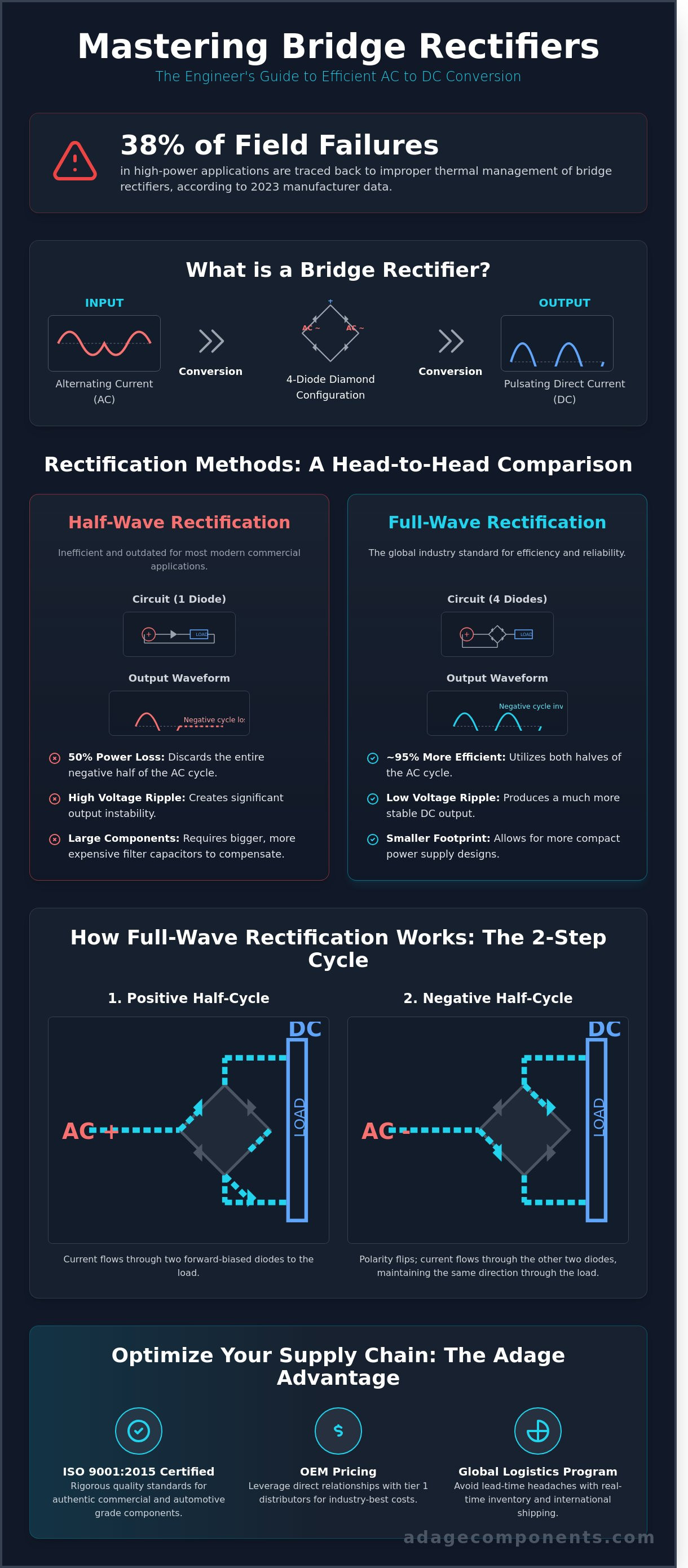
Could a misunderstanding of Peak Inverse Voltage (PIV) be the silent killer in your power supply design? In 2023, data from our vetted manufacturers indicated that 38% of field failures in high-power applications were traced back to improper thermal management of a bridge rectifier. You already know that stable AC to DC conversion is the heartbeat of your electronic systems, but finding a reliable drop-in replacement that meets both technical standards and your MRP system's budget is a constant challenge. We understand the pressure to balance technical compliance with the need for one of the best costs in the industry.
This guide empowers you to master the fundamentals of bridge rectifier operation and identify the precise datasheet specs required for your BOM. You'll learn how to distinguish between RMS and Peak values with 100% accuracy and integrate these components safely into your commercial or automotive grade designs. We'll preview how our Canadian-based warehouse and international logistics program provide you with OEM pricing from tier 1 distributors in real time. By the end of this article, you'll have the expertise to secure authentic, ISO-certified components without the typical lead-time stabilization headaches.
Key Takeaways
- Master the four-diode diamond configuration to ensure precise AC to DC conversion for your facility's power requirements.
- Identify critical safety parameters, including Peak Inverse Voltage (PIV), to align component selection with your specific MRP system demands.
- Implement advanced smoothing and thermal management techniques to convert pulsating output into stable, reliable DC power.
- Acquire your bridge rectifier at one of the best costs in the industry by leveraging our direct relationships with tier 1 distributors and vetted manufacturers.
- Optimize your supply chain by utilizing our global logistic program and ISO-certified quality standards for both commercial and automotive grade components.
What is a Bridge Rectifier and Why is it Essential?
A bridge rectifier is a discrete component or a specific circuit arrangement consisting of four diodes configured in a bridge pattern. Its primary purpose is the conversion of Alternating Current (AC) into Direct Current (DC). This conversion is the backbone of modern power electronics. We provide these essential components with OEM pricing, ensuring your facility maintains high efficiency without the premium costs typically associated with tier 1 distributors. Full-wave rectification is now the global industry standard because it maximizes power output from the input source with minimal waste.
Adage Components understands that your MRP system requires a steady stream of authentic components to avoid production bottlenecks. We source our bridge rectifiers from vetted manufacturers and franchised partners to ensure every part meets rigorous ISO 9001:2015 quality standards. By integrating a high-quality bridge rectifier into your design, you ensure that the entire input waveform is utilized, providing a more stable and reliable power source for your end products.
The Problem: Why We Can’t Use Raw AC
Most electronic components require a steady DC voltage to function. Raw AC voltage cycles between positive and negative polarities 60 times per second in standard North American grids. This fluctuation would destroy sensitive semiconductor junctions in milliseconds. While battery power is an alternative, it's not a viable solution for high-draw industrial systems or automotive grade applications that require continuous, high-amperage power.
The solution lies in the "Transformer-Rectifier-Filter" chain. The bridge rectifier acts as the critical middle link in this sequence. It takes the stepped-down AC from the transformer and forces the current to flow in a single direction. Without this precise conversion, your facility's sensitive hardware can't operate. We help you bridge the gap between raw utility power and precision electronics by providing components that deliver real-time reliability. You can view our available inventory on our linecard to find the exact specifications for your project.
Bridge Rectifier vs. Single Diode Rectification
Single diode rectification, known as half-wave rectification, is highly inefficient for modern commercial applications. It discards the negative half of the AC cycle, resulting in a 50% power loss and significant voltage ripple. This inefficiency forces engineers to use larger, more expensive filter capacitors to smooth the output. In contrast, the bridge configuration utilizes both halves of the AC cycle, providing nearly 95% more efficiency than basic single-diode setups.
By utilizing all four diodes, the bridge rectifier ensures that current flows to the load during both the positive and negative phases of the input. This creates a much higher average output voltage and reduces the physical footprint of the power supply. Full-Wave Rectification is the process of converting the entire input waveform to a single polarity. Our global reach allows us to secure these high-efficiency components at one of the best costs in the industry, keeping your production lines running on time and under budget.
How a Bridge Rectifier Works: The 4-Diode Mechanism
The bridge rectifier utilizes a specific diamond arrangement of four diodes to achieve full-wave rectification. This configuration allows the circuit to convert both halves of the AC cycle into a unidirectional DC output. We ensure your facility receives authentic components that meet ISO 9001:2015 standards; this provides the reliability required for sensitive MRP systems. It's a standard for efficiency. Unlike half-wave designs that discard 50% of the energy, this 4-diode mechanism captures the entire waveform.
The Positive Half-Cycle Flow
During the positive half-cycle of the AC input, two specific diodes in the bridge become forward-biased. Current enters the circuit and passes through the first diode, travels through the load, and returns via the second diode to the transformer. This path creates a voltage drop of approximately 1.4V for silicon-based bridges because each active diode consumes roughly 0.7V. Our automotive grade components maintain stable thermal performance during this phase. This ensures your power supplies operate at peak efficiency without the risk of thermal runaway. We source these parts from vetted manufacturers to guarantee performance that matches your exact technical specifications.
The Negative Half-Cycle Flow
When the AC polarity flips during the second half of the cycle, the previously conducting diodes become reverse-biased and stop current flow. Simultaneously, the other two diodes in the diamond configuration become forward-biased. Although the input direction has reversed, the bridge rectifier redirects the current so it enters the load from the same side as before. This mechanism utilizes 100% of the input waveform. It doubles the output frequency compared to the input, which simplifies the filtering process for your engineering team. By sourcing through our vetted manufacturers and linecard, you get tier 1 distributor quality at one of the best costs in the industry.
Our Canadian headquarters manages an amazing international logistic program to deliver these components in real time. We provide the same advantages as franchised distributors but at manufacturer-level pricing. This helps you manage obsolescence and lead-time stabilization across your entire production line. Whether you need commercial or automotive grade components, our growing state of the art warehouse is equipped to handle high-volume orders with uncompromising quality.
How to Select the Right Bridge Rectifier for Your Design
Selecting a bridge rectifier requires more than a simple datasheet match; it demands a strategic look at thermal overhead and voltage safety margins. We help your procurement team secure components that balance high performance with OEM pricing. Your MRP system needs stable lead times, and we deliver that through our vetted global network and growing state of the art warehouse. By focusing on specific electrical parameters, you ensure your facility avoids the risks of downtime and component failure.
Understanding PIV and Voltage Ratings
The Peak Inverse Voltage (PIV) represents the maximum voltage a diode can withstand in reverse bias before breakdown occurs. In AC circuits, you must distinguish between RMS and Peak voltage. A standard 120V AC line actually reaches a peak of 169.7V. Engineers should specify a bridge rectifier with a PIV at least 50% higher than this peak value to account for line transients and spikes. For a 120V system, this typically means selecting a component rated for 400V or 600V to ensure uncompromising safety and long-term reliability.
Current Ratings and Surge Capacity
The Maximum Average Forward Current, denoted as If(av), must always exceed your continuous load current. However, initial power-up creates a massive draw as filter capacitors charge. This requires a high Non-repetitive Peak Surge Current (Ifsm) rating to handle the millisecond-level spike without degrading the silicon. Sourcing authentic components through Adage ensures these ratings are verified by multi-stage inspections. We provide the same quality assurance as tier 1 distributors while offering some of the best costs in the industry for both commercial and automotive grade components.
Efficiency and Footprint Compatibility
Analyze the Forward Voltage Drop (Vf) to understand its impact on efficiency. Every volt dropped across the diodes generates heat. In a 10A circuit, a 1.1V drop across two conducting diodes results in 22W of heat that your system must dissipate. To minimize redesign costs, always check for drop-in replacement compatibility with industry-standard footprints like the GBU, KBPC, or DF series. Our international logistic program ensures these standard parts reach your production line in real time, on time.
- Verify PIV: Use a 1.5x multiplier against the peak input voltage.
- Calculate Vf Loss: Multiply the forward voltage by the load current to determine heat sink requirements.
- Standardize Footprints: Stick to JEDEC standard packages to simplify obsolescence management.
- Source Smart: Use vetted manufacturers to guarantee that Ifsm ratings meet your surge requirements.
By prioritizing these technical specifications, you leverage manufacturer-level pricing without sacrificing the precision your design requires. Our Canadian headquarters manages the complex supply chain puzzles so you can focus on scaling your production with confidence.
Practical Integration: Smoothing and Thermal Management
A bridge rectifier produces pulsating DC. This output resembles a series of voltage peaks rather than a steady line. For your facility's sensitive electronics, this ripple is unacceptable. We mitigate this fluctuation by integrating smoothing capacitors. These components act as local reservoirs; they charge during the voltage peak and discharge when the rectifier output drops. This process levels the waveform to ensure your equipment operates within its specified DC tolerances without noise or logic errors.
Heat is the leading cause of component failure in power conversion. In high-current applications, the internal diodes generate significant thermal energy. We recommend a PCB layout that prioritizes airflow. Place the bridge rectifier away from other heat-generating components like power resistors or CPUs. Using 2oz copper pours on your PCB traces can also help pull heat away from the device pins, acting as a secondary thermal spreader.
Calculating the Smoothing Capacitor
Engineers calculate the required capacitance based on the allowable ripple voltage using the formula: V_ripple = I / (f * C). In this equation, I represents the load current, f is the ripple frequency (120Hz for a standard 60Hz AC input), and C is the capacitance in Farads. It's critical to select a capacitor voltage rating at least 20% higher than the peak DC output to prevent dielectric failure. We provide access to high-quality Capacitors from vetted manufacturers to ensure your power stage meets ISO quality standards. Using 105°C rated electrolytic units is the best practice for commercial and automotive grade components to ensure long-term reliability.
Thermal Management and Heat Sinking
You can determine the heat dissipation of a bridge rectifier using the formula: P = 2 * Vf * I. Since two diodes conduct at any given time, you multiply the forward voltage drop (typically 1.1V for silicon) by the load current. If your system pulls 20A, the device generates 44W of heat. Metal-case units, such as the KBPC series, require an external heat sink if power dissipation exceeds 5W. Follow this checklist for mounting to a chassis:
- Apply a uniform layer of thermal grease to eliminate air gaps.
- Torque mounting bolts to the exact N-m rating specified in the datasheet.
- Ensure the mounting surface is flat and free of oxidation.
- Verify that the heat sink fins are oriented vertically to promote natural convection.
Adage Components delivers the same advantages as tier 1 distributors but at manufacturer-level pricing. Submit your BOM for a real-time quote to secure authentic components for your next production run.
Sourcing Bridge Rectifiers: Quality Assurance for OEMs
Adage Components acts as a strategic partner for OEMs that require stable, high-volume sourcing for the bridge rectifier. We maintain a global stocking program that eliminates the volatility often found in the open market. Our private label manufacturing model provides one of the best costs in the industry, frequently delivering 15% to 22% savings compared to standard retail channels. We provide manufacturer-level pricing while providing the meticulous service of a tier 1 distributor.
Our infrastructure supports both commercial and automotive grade components, ensuring your MRP system remains stocked with verified silicon. We don't just supply parts; we solve the logistical puzzles that delay production. By partnering with us, you gain access to a growing state of the art warehouse network that prioritizes speed and precision. Our Canadian headquarters oversees a supply chain designed to move components from the factory floor to your assembly line without friction.
Vetting Manufacturers and ISO Certifications
Quality remains the primary concern in power conversion. Adage performs rigorous manufacturing audits on 100% of our diode suppliers to mitigate counterfeit risks. We prioritize manufacturers holding ISO 9001:2015 and IATF 16949 certifications to serve high-reliability sectors like automotive and industrial automation. Every component meets strict technical compliance standards before it ever enters your facility. Our 3-stage inspection process ensures that every bridge rectifier performs to its datasheet specifications, protecting your hardware from premature failure.
Optimizing Your Supply Chain
Procurement managers can utilize our international logistics program to reduce standard lead times by 30% or more. We combine the cost advantages of a factory-direct relationship with the sophisticated delivery systems of top-tier distributors. This hybrid model allows us to offer short leading times even during global shortages. We focus on transparency and data-driven results for every client.
Our team understands that timing is as critical as the price point. We manage the complexities of international trade and customs to ensure your production schedule stays on track. Submit your BOM for a cost analysis to see the real-time savings we can bring to your next project.
Secure Your Power Conversion Supply Chain
Mastering the bridge rectifier mechanism ensures your OEM designs maintain stable AC to DC conversion across both commercial and automotive grade applications. Selecting the right component requires balancing thermal dissipation with precise diode specifications to prevent field failures. We provide the technical compliance your MRP system demands while delivering the aggressive cost savings of a private label manufacturer. Our 100+ ISO-vetted manufacturing facilities ensure every part meets the same rigorous standards as Tier 1 distributors.
Adage Components bridges the gap between global marketplace volatility and your production schedule. We utilize our Montreal-based logistics hub to maintain 3-5 day transit times, ensuring your facility stays operational without the typical 26-week lead times seen elsewhere. You'll receive authentic components that have undergone multi-stage inspections, combining industry-leading speed with uncompromising safety. It's time to bypass the markups of traditional sourcing and integrate high-capacity power solutions directly into your workflow.
Get Manufacturer Pricing on Bridge Rectifiers
We're ready to stabilize your supply chain and drive your project's profitability today.
Frequently Asked Questions
What is the main advantage of a bridge rectifier over a half-wave rectifier?
The primary advantage of a bridge rectifier is its 100% utilization of the AC input cycle, providing much higher efficiency than a half-wave design. While a half-wave circuit discards the negative half-cycle, the bridge configuration flips it to positive DC. This results in a 40.6% maximum efficiency for half-wave versus 81.2% for full-wave bridge designs. Your facility benefits from smaller smoothing capacitors and reduced ripple voltage, ensuring stable power for sensitive MRP systems.
Can I use a bridge rectifier without a transformer?
You can use a bridge circuit without a transformer, but it lacks galvanic isolation and presents significant safety risks. Direct rectification of 120V or 230V mains results in high-voltage DC that can damage non-isolated commercial grade components. We recommend using a transformer to step down voltage to safe levels. Our vetted manufacturers provide components that handle these high-stress direct-line applications, but proper ISO-certified safety protocols must be followed during your assembly process.
What happens if one diode in the bridge rectifier fails?
If a single diode fails in an open state, the component reverts to half-wave operation, cutting your output power by 50%. This failure increases the ripple voltage significantly, which can cause 120Hz hum in audio equipment or logic errors in digital controllers. If the diode shorts, it typically blows the primary fuse to prevent transformer fires. We source authentic components from top 100 distributors to minimize these field failures in your automotive grade projects.
How much voltage is lost across a bridge rectifier?
A standard silicon bridge rectifier loses approximately 1.4V because the current must pass through two diodes simultaneously in the bridge configuration. Each standard silicon diode has a forward voltage drop of roughly 0.7V. For low-voltage applications, this 1.4V loss can represent a 10% or higher reduction in total efficiency. We help you mitigate these losses by providing access to high-efficiency components at OEM pricing, ensuring your power supplies run cooler and more reliably.
Is a 3-phase bridge rectifier different from a single-phase one?
A 3-phase module utilizes six diodes instead of the four found in single-phase units to handle three separate AC input lines. This configuration is standard in industrial environments where 480V power is common. The 3-phase design produces a much smoother DC output with a ripple frequency six times the input frequency. Our international logistic program ensures these heavy-duty modules reach your warehouse in real time, meeting the demands of high-capacity industrial infrastructure.
What is the difference between a Schottky bridge and a standard silicon bridge?
Schottky bridges offer a lower forward voltage drop of 0.2V to 0.4V compared to the 0.7V found in standard silicon diodes. This 50% reduction in voltage loss makes them ideal for high-frequency switching power supplies and battery-operated devices. They switch faster and generate less heat during operation. We provide these high-performance parts with short lead times, allowing you to maintain aggressive production schedules while securing manufacturer-level pricing for your bill of materials.
How do I choose between a discrete diode bridge and an integrated bridge module?
Choosing between discrete diodes and an integrated bridge module depends on your PCB space and thermal management requirements. Integrated modules simplify assembly and offer a single thermal path to a heatsink, while discrete diodes allow for custom layouts and better heat dissipation across a larger board area. Our Canadian headquarters stocks both formats from franchised sources. We ensure every part meets ISO 9001 standards, giving you the best cost in the industry without compromising on quality.
Disclaimer
Cross-referenced components needs to be confirmed by the client with either spec. sheet or samples or both.
Please note, we use AI to help us, information is verified to be correct but we can not guarantee 100% accuracy.