
With over 3,000 chip resistors in every modern electric vehicle, a single thermal oversight can compromise an entire automotive platform. You likely already know that standard datasheet ratings are often misleading when applied to high-density industrial environments or volatile ambient conditions. Understanding how to calculate resistor power dissipation is only the first step; you must also navigate the complex thermal derating curves and the July 2026 RoHS lead exemption deadlines that are currently reshaping the global supply chain. At Adage Components, we provide the technical expertise and manufacturer pricing that Tier 1 distributors often lack, ensuring your designs remain both compliant and cost-effective.
We'll help you master the essential formulas and thermal principles required to ensure long-term component reliability in the most demanding applications. You're going to learn how to move beyond basic math to implement rigorous derating strategies that protect your hardware from thermal stress. This guide provides a professional briefing on accurate power calculations, strategic component selection, and logistical methods to reduce your BOM costs through our state-of-the-art warehouse and international logistics program. We're committed to delivering authentic, vetted components that integrate seamlessly with your existing MRP system requirements.
Key Takeaways
- Learn exactly how to calculate resistor power dissipation using P = VI and its derived formulas to establish a baseline for component safety.
- Understand the 70°C rule and thermal derating curves to prevent catastrophic failure in high-stress automotive and industrial applications.
- Evaluate the specific power-handling benefits of thick film versus wirewound technologies to make informed selections for your hardware.
- Reduce BOM costs by leveraging manufacturer pricing and our state-of-the-art warehouse for a more efficient procurement process.
- Streamline your supply chain using Adage Components' international logistics program to ensure your MRP system stays synchronized with on-time deliveries.
Fundamentals of Power Dissipation in Resistors
Resistors don't just limit current; they act as energy converters. Every time current passes through a resistive element, a portion of that electrical energy transforms into heat. This process, known as Joule heating, is a core concept in the Fundamentals of Power Dissipation in Resistors. If this heat isn't managed or dissipated effectively, the internal temperature of the component rises until it reaches a point of physical degradation. For high-stakes industrial applications, failing to account for this thermal energy leads to catastrophic system failure.
Engineers must understand how to calculate resistor power dissipation to ensure that every component stays within its safe operating area. Manufacturers define a maximum power rating, or wattage, which represents the highest amount of energy the resistor can dissipate at a specific ambient temperature without sustaining damage. Adage Components provides the technical documentation and manufacturer pricing required to verify these limits across our entire line of commercial and automotive grade components. Precision in these initial calculations is the only way to avoid the reliability gaps often found in unoptimized supply chains.
To better understand the relationship between electrical energy and heat, watch this helpful technical briefing:
The Physics of Joule Heating
At the atomic level, Joule heating occurs when moving electrons collide with the ions that make up the resistor's conductive material. These collisions transfer kinetic energy to the lattice structure, manifesting as thermal energy. A component's power rating is essentially its capacity to reach thermal equilibrium, where the rate of heat generation equals the rate of heat lost to the surrounding environment. If the generation rate exceeds the dissipation rate, the component enters a state of thermal runaway. We source our Thick Film and Thin Film resistors from vetted manufacturers who rigorously test these thermal limits to ensure they meet the demands of modern, high-density PCB architectures.
Why Power Calculations Matter for OEMs
For an OEM, accurate power calculations are directly linked to the Mean Time Between Failures (MTBF). Exceeding power limits doesn't always result in immediate smoke or fire; more often, it causes subtle resistance drift or substrate cracking. These defects lead to intermittent signal errors that are difficult to diagnose in the field. By mastering how to calculate resistor power dissipation, procurement and engineering teams can select components that maintain stability over the long term. This disciplined approach is vital for meeting ISO certifications and automotive standards. Adage Components supports these efforts by offering a comprehensive BOM cost analysis, identifying where high-power components can be optimized for both reliability and cost. Our state-of-the-art warehouse ensures that these critical parts are delivered on time, keeping your MRP system synchronized and your production lines moving.
How to Calculate Resistor Power Dissipation: The Core Formulas
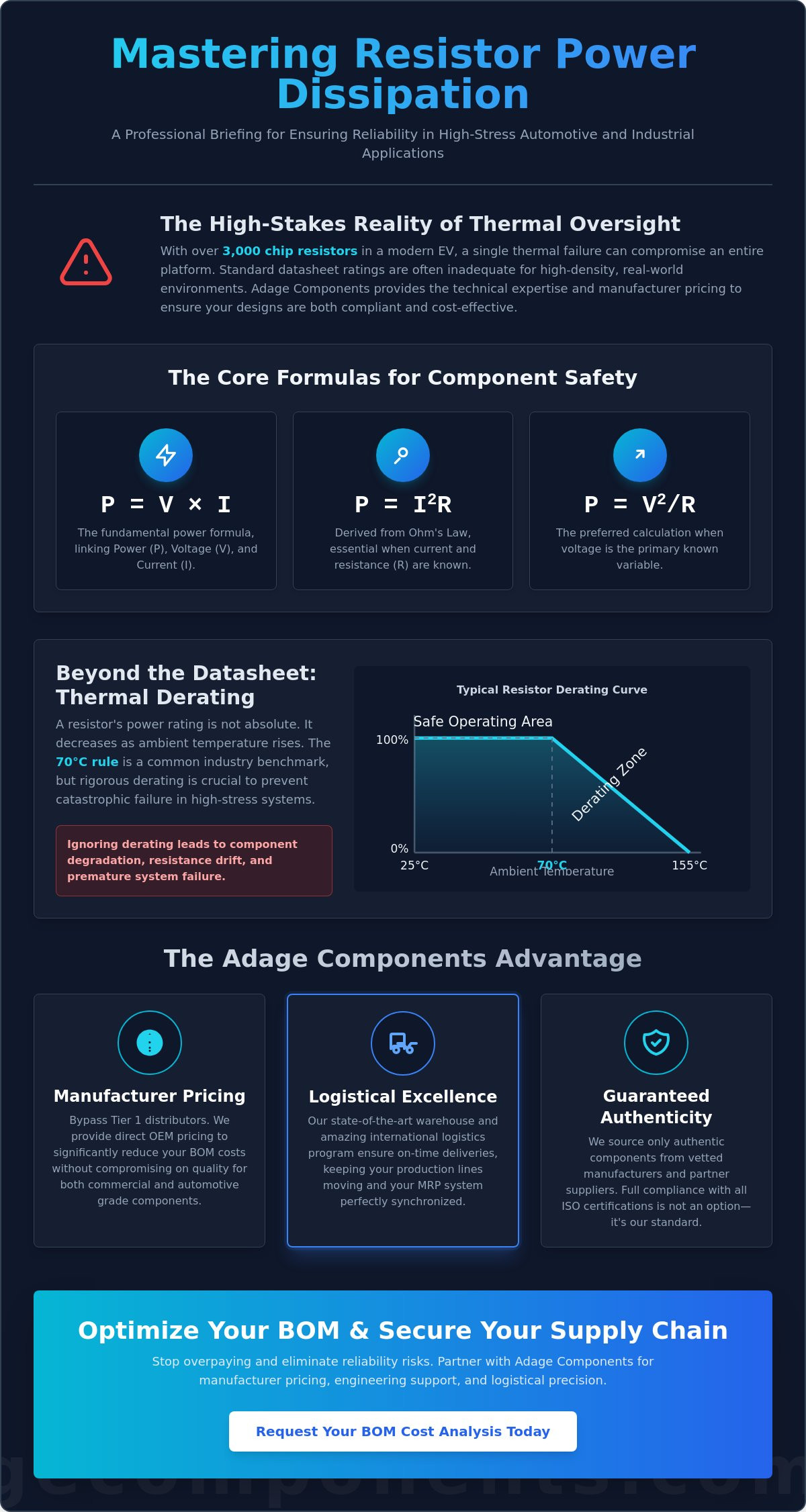
Precision in component selection starts with a clear understanding of the mathematical foundations. The primary method for determining energy loss is the Power Formula: P = V × I, where Power (Watts) equals Voltage (Volts) multiplied by Current (Amperes). While this provides a direct snapshot of energy conversion, real-world engineering often requires secondary derivations based on Ohm’s Law. By substituting V = IR or I = V/R into the primary equation, we arrive at the two most functional formulas for industrial design: P = I²R and P = V²/R.
Knowing how to calculate resistor power dissipation accurately allows procurement teams to avoid over-specifying components. This directly reduces BOM costs while maintaining safety margins. For instance, consider a standard 12V automotive circuit utilizing a 10 Ω resistor. Using the voltage-based formula, the dissipation is (12²) / 10 = 14.4 Watts. This immediately signals the need for a high-wattage wirewound resistor rather than a standard chip resistor. Before finalizing this selection, engineers must also consult resistor thermal derating curves to account for the high ambient temperatures found in engine compartments.
Calculating Power with Current and Resistance (P = I²R)
This formula is the industry standard for Current Sensing Resistors and power supply designs where the current is the primary controlled variable. It's critical to remember the "Square Law" effect. If the current through a circuit doubles, the power dissipation quadruples. This exponential increase is why current-sensing applications require high-precision, low-resistance components that can handle sudden surges without shifting out of tolerance. We provide authentic, vetted components that undergo rigorous testing to ensure they handle these current-heavy loads without resistance drift.
Calculating Power with Voltage and Resistance (P = V²/R)
When dealing with fixed voltage rails, such as pull-up resistors or voltage dividers, this formula is the most efficient choice. It highlights how sensitive a system is to voltage fluctuations. A minor spike in the supply rail can lead to a significant increase in thermal stress. Use this calculation when your supply voltage remains constant and the resistance value is already defined in your MRP system. Adage Components ensures that all our metal film and thin film resistors maintain strict resistance tolerances. This keeps your calculations reliable across the entire product lifecycle, offering manufacturer pricing that beats franchised distributors.
Thermal Derating: Adjusting for Real-World Environments
Calculating the theoretical wattage is just the beginning. In practice, a resistor's ability to shed heat depends entirely on its environment. This is where thermal derating becomes a critical design factor. Thermal derating is the intentional reduction of a component's maximum power rating as the ambient temperature increases. If you only rely on the basic steps of how to calculate resistor power dissipation without accounting for ambient heat, you risk premature component failure in the field. This is a common oversight that leads to costly recalls and maintenance cycles.
Most standard resistors follow the '70°C Rule.' This industry benchmark indicates that a resistor can operate at its full rated power up to an ambient temperature of 70°C. Once the environment exceeds this threshold, the component's capacity to dissipate heat safely begins to plummet. Factors such as restricted airflow within an enclosure, the thickness of the PCB copper traces, and heat radiation from adjacent high-power components all accelerate this decline. For high-reliability systems, we recommend a safety margin of at least 50%. This means selecting a resistor with a power rating double what your initial calculations suggest. Adage Components ensures that all our commercial and automotive grade components are tested to withstand these rigorous real-world conditions.
Reading a Resistor Derating Curve
Datasheets include a derating curve that is essential for professional component selection. The X-axis represents the ambient temperature, while the Y-axis shows the percentage of the nominal power rating. The most important feature is the 'knee' of the curve. This is the specific temperature point where the line begins its downward slope. If your operating environment is 100°C or 125°C, you must calculate the effective power rating by multiplying the nominal wattage by the percentage shown on the Y-axis at that temperature. Neglecting this step often leads to resistance drift or substrate cracking in high-density architectures.
Environmental Factors in Industrial Enclosures
High-density PCB layouts often create pockets of stagnant air that trap heat. In these scenarios, even a well-ventilated enclosure can have localized 'hot spots' that exceed the 70°C threshold. Strategic sourcing helps mitigate this risk. Because Adage Components offers manufacturer pricing, procurement teams can often over-specify resistor wattage without exceeding the project budget. This provides a significant reliability buffer compared to using minimum-spec parts from Tier 1 distributors. If you need assistance with complex thermal modeling or BOM optimization, our team provides expert Adage Components Technical Support. We help you integrate these high-reliability components into your MRP system to ensure your production remains both on time and within spec.
Selecting the Right Resistor Technology for Your Power Needs
Selecting the right technology is as critical as the initial math. While you now know how to calculate resistor power dissipation, applying those figures to the wrong material substrate will still lead to component failure. Thick film technology currently holds 43% of the market share because it offers a versatile balance of power density and cost. However, high-precision or high-surge applications require more specialized solutions like thin film, MELF, or wirewound resistors. Each has a distinct thermal profile that dictates its suitability for your specific environment.
Adage Components acts as a strategic partner, ensuring you don't just find a part, but the exact technical match for your design. Our private-label manufacturing audits guarantee that every component meets the rigorous standards required for automotive and industrial grade certification. We provide a bridge between a fragmented marketplace and your specific technical needs, offering manufacturer pricing that bypasses the high margins of Tier 1 distributors. This disciplined approach to sourcing ensures your hardware remains reliable throughout its entire lifecycle.
Thick Film Chip Resistors: The OEM Workhorse
Thick film resistors are the reliable backbone of most industrial PCB designs. They provide a high power-to-size ratio, making them the default choice for general-purpose applications where cost and space are primary concerns. We maintain a massive inventory of these components in our state-of-the-art warehouse to support your MRP system requirements. Whether you need standard commercial parts or AEC-Q200 qualified automotive grade components, our Thick Film Chip Resistors linecard offers the best cost in the industry with short lead times.
Precision and High-Power Alternatives
When your design demands superior heat handling or surge resistance, moving beyond thick film is necessary. Wirewound resistors are the definitive solution for high-wattage and high-surge loads. Their physical construction allows for massive heat dissipation and superior pulse handling. For automotive and medical designs where reliability is non-negotiable, MELF (Metal Electrode Leadless Face) resistors offer superior thermal stability and moisture resistance compared to standard flat chips. With modern vehicles incorporating over 3,000 chip resistors on average, the thermal stability of MELF components is a key differentiator for long-term reliability.
Sourcing these specialized components through Adage Components ensures you receive authentic parts from vetted manufacturers. We specialize in finding drop-in replacements for Tier 1 brands, allowing you to maintain your quality standards while achieving significant BOM cost savings. Our international logistics program ensures these critical parts reach your facility in real time, on time. Explore our full range of high-reliability components on our electronic components linecard.
Strategic Sourcing: Optimizing BOM Costs and Lead Times
Engineering precision is only half the battle. Once you understand how to calculate resistor power dissipation for your specific application, the focus shifts to sourcing these high-wattage components without inflating your Bill of Materials (BOM). In a volatile global market, procurement teams often face a choice between the high markups of franchised distributors or the risks of unvetted secondary markets. Adage Components eliminates this compromise by providing a superior alternative to Tier 1 distributors, offering manufacturer pricing on both commercial and automotive grade components. We act as a steady and meticulous partner, ensuring that the technical requirements of your design are matched by the logistical efficiency of your supply chain.
Our strategic approach moves beyond mere transactions. We thrive on solving difficult sourcing puzzles, specifically for high-power resistors that often carry long lead times at major distributors. By integrating Adage sourcing with your existing MRP system, we create a seamless procurement flow that reduces cognitive load on your team. Our amazing international logistics program is designed to deliver products to your facility in real time, on time, maintaining the pulse of your production line without the friction of traditional distribution models.
Manufacturer Pricing vs. Tier 1 Distribution
Adage Components provides the same high-quality passives found at Tier 1 distributors but at OEM pricing. We eliminate the distributor markup by leveraging our infrastructure as a private label manufacturer. This allows us to offer the best cost in the industry for thick film, thin film, and wirewound resistors. Our global stocking programs are essential for risk mitigation, providing a buffer against the supply chain disruptions that frequently affect the electronics industry. To learn more about how we support high-volume requirements, explore our Distributor Affiliated Program. This disciplined expertise ensures your project stays under budget while maintaining peak performance.
Ensuring Quality Through Vetted Sourcing
Reliability is our primary metric. Every component we supply is authentic and sourced from vetted manufacturers and partner suppliers who comply with all ISO certifications. Our manufacturing audits are rigorous, ensuring that the power ratings you used when learning how to calculate resistor power dissipation are backed by physical reality. We don't just ship parts; we provide components that have passed through our state-of-the-art warehouse and multi-stage inspection processes. This commitment to integrity is why leading OEMs trust us for their high-stakes industrial and automotive designs. To see the immediate impact on your bottom line, we invite you to submit your BOM for a cost-savings analysis. We provide a detailed breakdown that identifies optimization opportunities for both cost and technical reliability.
Securing Your Supply Chain Through Technical Precision
Achieving long-term reliability in automotive and industrial designs requires more than a basic mathematical exercise. You've learned how to calculate resistor power dissipation using core formulas, but true success depends on applying rigorous thermal derating and selecting the right material technology for your specific environment. By accounting for the 70°C rule and maintaining a 50% safety margin, you protect your hardware from the thermal stress that causes resistance drift and catastrophic field failures.
The pursuit of hardware reliability isn't limited to industrial components; in the consumer tech sector, retailers like Devia Canada focus on delivering high-performance mobile accessories and audio equipment built for durability.
Adage Components acts as your strategic partner to move these designs into production without the typical distributor markup. We provide direct OEM pricing on Thick Film resistors and precision passives, ensuring your BOM remains competitive. Our ISO Certified Quality Management and state-of-the-art warehouse operations guarantee authenticity, while our international logistics program delivers industry-leading short lead times. It's time to bypass Tier 1 margins and secure a reliable component flow that integrates seamlessly with your MRP system.
Request a Quote for Manufacturer-Direct Resistors and optimize your procurement strategy today. We're ready to support your next high-reliability project.
Frequently Asked Questions
What happens if a resistor exceeds its power rating?
Physical degradation occurs immediately, typically starting with a permanent shift in resistance value known as drift. If the heat generation continues to exceed the component's ability to dissipate it, the ceramic substrate can crack or the resistive film may burn out entirely. This creates an open circuit that compromises the long-term reliability of your hardware. Adage Components ensures all supplied parts are vetted to prevent these failures in high-stakes industrial systems.
How do I calculate power dissipation in a series circuit?
Calculate the power for each individual resistor by first determining the total current flowing through the loop. Since current is identical for all components in series, use the formula P = I²R for each part. Summing these individual values gives the total circuit dissipation. Knowing how to calculate resistor power dissipation for each specific part ensures you don't over-stress a single low-wattage component within the chain.
How do I calculate power dissipation in a parallel circuit?
Use the voltage-based formula P = V²/R for each branch because the voltage across parallel components remains constant. Alternatively, you can find the individual current through each branch and apply P = VI. This method is essential when designing power distribution networks. It ensures each branch handles its thermal load without radiating excessive heat to adjacent components, which we verify through our rigorous BOM cost analysis.
What is the difference between rated power and actual power dissipation?
Rated power is the maximum wattage a manufacturer guarantees under ideal laboratory conditions, while actual power dissipation is the real-time energy conversion occurring in your circuit. The rated power is a theoretical limit found in the datasheet. Your actual dissipation must always remain significantly lower than this rated limit, especially after applying the thermal derating factors required for real-world industrial environments.
How does ambient temperature affect resistor wattage?
High ambient temperatures reduce a resistor's effective wattage by limiting its ability to transfer heat to the surrounding air. As the environment gets hotter, the thermal gradient decreases, which forces the component to run at a lower power level to avoid damage. Adage Components provides the technical data and ISO certified quality assurance required to verify these limits, ensuring your MRP system reflects the correct specifications for harsh environments.
Can I use a higher wattage resistor than what is calculated?
Yes, using a resistor with a higher wattage rating is a standard engineering practice to increase system reliability. A higher-rated component typically has a larger surface area, allowing it to operate at lower temperatures for the same power load. Because Adage Components offers manufacturer pricing, procurement officers can often upgrade to these higher wattage parts without the cost penalties typically associated with franchised distributors.
How do I find the power rating of a surface mount (SMD) resistor?
The power rating of an SMD resistor is primarily determined by its package size, such as 0603 or 1206. Larger packages provide more surface area for heat dissipation. However, you must consult the specific datasheet, as different technologies like thin film or thick film offer varying power densities. We maintain full traceability in our state-of-the-art warehouse to ensure you receive authentic components that match your exact power requirements.
What safety margin should I use for resistor power dissipation?
A safety margin of 50% is the recommended standard for high-reliability industrial and automotive applications. If your initial math shows how to calculate resistor power dissipation at 0.125W, you should select a component rated for at least 0.25W. This buffer accounts for unexpected voltage spikes and stagnant air within enclosures. Our international logistics program ensures these higher-spec components reach your facility on time, keeping your production lines moving.
Disclaimer
Cross-referenced components needs to be confirmed by the client with either spec. sheet or samples or both.
Please note, we use AI to help us, information is verified to be correct but we can not guarantee 100% accuracy.


