

What if a diode could tune an RF circuit without a mechanical adjustment? A varactor diode does this by converting reverse-bias voltage into adjustable junction capacitance. Increase the reverse voltage, and the depletion region widens, reducing capacitance. The principle is straightforward, but predicting its effect on circuit performance takes a closer look.
If reverse bias is confusing or datasheet values are difficult to connect to real RF behavior, you’re not alone. A capacitance range by itself doesn’t tell you whether a part will meet your circuit’s needs. Quality factor, tuning ratio, series resistance, voltage limits, and parasitic effects also matter.
This guide explains how voltage-controlled capacitance works, where varactors are used in RF tuning, and which specifications to compare with your circuit conditions. You’ll also learn about practical limitations and what to verify during component qualification, keeping electrical suitability separate from sourcing checks. The goal is a clear basis for evaluating a varactor diode before selecting a part.
Key Takeaways
- A varactor diode uses reverse bias to adjust junction capacitance, making it useful for electronic tuning in RF circuits.
- Its capacitance changes nonlinearly with voltage, so check the device-specific curve rather than assuming a fixed response.
- Compare datasheet specifications with your circuit’s tuning range and performance requirements before choosing a component.
- Plan the bias network and RF signal path, then verify tuning behavior on the bench.
- Keep electrical qualification separate from supplier checks, including manufacturer identity, datasheet revision, traceability, and required quality documentation.
What Is a Varactor Diode? The Voltage-Controlled Capacitor Explained
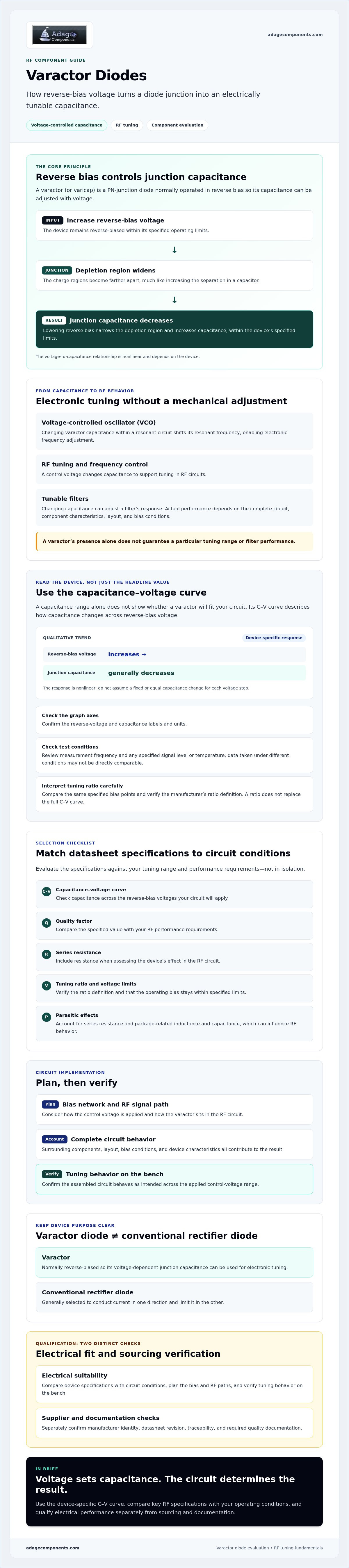
A varactor diode is a PN-junction semiconductor operated in reverse bias so its junction capacitance can be adjusted by changing the applied voltage. Also called a varicap diode, it acts as an electrically controlled capacitor in RF circuits rather than primarily as a rectifier.
Why a reverse-biased junction behaves like a capacitor
A reverse-biased PN junction has a depletion region between its positive and negative charge regions. This region acts like the dielectric separation in a capacitor, while the charge regions on either side act like capacitor plates. The analogy explains the principle, although a semiconductor junction is not a conventional pair of metal plates.
As reverse-bias voltage rises, the depletion region widens. The charge regions are then farther apart, so junction capacitance decreases. Reducing the reverse bias narrows the depletion region and increases capacitance, within the device’s specified operating limits. The relationship is nonlinear and depends on the junction design, so check the device’s capacitance-voltage curve in its datasheet.
A real device also has parasitic effects, including series resistance and package-related inductance and capacitance. These can influence circuit behavior, particularly at RF frequencies. For a broader overview of the operating principle, naming, and applications, see this reference on the varactor diode.
Where varactor diodes are used
Electronic tuning is the core application. In a voltage-controlled oscillator (VCO), a control voltage changes the varactor’s capacitance within a resonant circuit. This shifts the circuit’s resonant frequency, allowing electronic frequency adjustment without mechanically changing a tuning element.
The same principle supports RF tuning and frequency-control circuits. Varactors may also be used in tunable filters, where changing capacitance can adjust a filter’s response. The result depends on the complete circuit, including the varactor’s characteristics, surrounding components, layout, and bias conditions. A component’s presence alone doesn’t guarantee a particular tuning range or filter performance.
In contrast, a conventional rectifier diode is generally selected to conduct current in one direction and limit it in the other. A varactor is normally kept reverse-biased so the circuit can use its voltage-dependent junction capacitance. This distinction helps identify the device function before evaluating its electrical specifications.
How Varactor Diode Capacitance Changes with Reverse-Bias Voltage
Reverse bias changes junction capacitance by widening the depletion region between the PN junction’s charge regions. This increases their effective separation, so higher reverse voltage generally means lower junction capacitance. The relationship isn’t linear, and each device has its own capacitance-voltage (C-V) response.
That curve matters in circuit design. A control-voltage change won’t necessarily produce an equal or predictable capacitance change across the full operating range. Use the manufacturer’s C-V data to estimate how capacitance shifts across the reverse-bias voltages your circuit will apply.
Reading a capacitance-voltage curve
Start by checking the graph axes. Reverse voltage is usually plotted horizontally and capacitance vertically, but confirm the labels and units. Then review the stated test conditions, including measurement frequency and any specified signal level or temperature. C-V data measured under different conditions may not be directly comparable.
A datasheet curve represents the specified device under its stated test conditions, not a universal response for every varactor. The Varactor diode uses reference from Georgia State University provides additional background on the physics and tuning principle.
What tuning ratio tells you
Tuning ratio compares capacitance at two specified reverse-bias conditions. It indicates how much capacitance changes across that voltage interval, but the term alone may not identify which voltages or ratio convention the manufacturer used. Check the datasheet’s definition and compare the same bias points when evaluating candidate devices. A ratio doesn’t replace the full C-V curve, which shows how capacitance behaves between those points.
How junction design shapes the response
Manufacturers can use different doping profiles to shape the C-V relationship. Abrupt and hyperabrupt junction profiles are two design approaches that influence how capacitance changes as reverse bias varies. Neither label alone tells you whether a part fits a particular circuit. Review the device-specific curve, specified operating limits, and manufacturer documentation.
Use those details to confirm that the required capacitance range is available within the circuit’s permitted bias conditions. For sourcing context, Adage’s listed diode categories show its represented diode offerings. Varactor diodes aren’t among the listed categories.
Varactor Diode Selection: Compare the Specifications That Affect RF Performance
Start with the circuit’s required capacitance range and operating frequency, then check whether a candidate part can meet both across the intended bias conditions. A high maximum capacitance alone isn’t enough. The circuit must also reach its required minimum capacitance and tune effectively across the full range.
Compare datasheet values at the stated reverse-bias voltages and matching test conditions. Measurement frequency, temperature, and method can affect the comparison, so check them before judging two candidates. Georgia State University provides a concise overview of voltage-controlled capacitance and its role in electronic tuning.
| Specification | Circuit-design implication |
|---|---|
| Capacitance range | Confirms whether the device spans the circuit’s required capacitance at the specified bias voltages. |
| Tuning ratio | Shows the capacitance change between defined bias points. Check the datasheet’s exact definition and endpoints. |
| Reverse-voltage limits | Keep the applied bias within the manufacturer’s operating and maximum ratings. |
| Q factor | Indicates reactive performance relative to loss at the stated conditions. Check that it suits the intended RF application. |
| Series resistance | Contributes to loss and can affect circuit performance, particularly at higher frequencies. |
Match tuning needs to circuit conditions
Evaluate capacitance under the operating-frequency conditions your design requires, not just at a convenient point on the datasheet curve. The tuning ratio summarizes the change between two specified bias voltages, but it can’t replace checking the full capacitance range. Confirm that both endpoints and the response between them meet the circuit’s tuning requirement.
Check losses, voltage limits, and test conditions
For a varactor diode, Q factor and series resistance help assess losses in the intended RF circuit. Compare these parameters at the relevant frequency and review any stated temperature and measurement conditions. Verify that the circuit’s bias stays within the specified reverse-voltage limits, including expected operating variation.
Finally, account for the complete RF layout. Package parasitics and board-level interconnects can add capacitance or inductance and alter circuit behavior, so a datasheet value doesn’t describe the assembled circuit by itself. Confirm performance in the intended layout and under representative operating conditions.
How to Use a Varactor Diode in an RF Circuit
Applying a varactor diode requires coordinated design of its control-voltage path and RF signal path. The bias network sets the reverse voltage that controls capacitance, while the RF path carries the signal through the tuned circuit. In practical wireless equipment and telecommunications systems—such as those relying on RF infrastructure components from Telco Antennas—ensuring clean isolation between tuning controls and RF pathways is essential. Choose specific component values and a topology only after checking the device datasheet and design requirements.
Set up the tuning voltage and RF path
Before building, confirm the diode’s reverse-bias operating range and other relevant limits in its datasheet. The bias network must deliver the required control voltage without allowing the control source to interfere with the RF signal. The RF path must let the tuned signal interact with the varactor while limiting unwanted coupling into the control path. The exact implementation depends on circuit topology and frequency.
Verify tuning range and stability in the assembled circuit
Use this workflow to move from requirements to bench verification:
- Define the target. Specify the required frequency range or filter response and the control-voltage range the circuit can provide.
- Check device limits. Confirm the chosen component’s capacitance data, bias conditions, and reverse-voltage limits before applying voltage.
- Plan signal and bias paths. Review how the RF signal reaches the tuned network and how the bias network supplies control voltage without creating an unintended signal path.
- Review layout risks. Assess nearby conductors and components for parasitic capacitance, inductive effects, noise pickup, and unwanted coupling between RF and control paths.
- Measure on the bench. Sweep the control voltage across the intended range and measure oscillator frequency or filter response. Compare the results with simulation and datasheet data under comparable conditions.
Bench results can differ from an ideal schematic. Board layout, component placement, and parasitic capacitance can shift the tuning response. Noise on the control voltage may also affect circuit stability, so inspect the control signal as well as the RF output. If measurements depart from expectations, check the test setup and layout before concluding that the component itself is unsuitable.
For related diode categories represented by Adage Components, review the diode offerings on our line card. Varactor diodes are not among the listed categories.
From Varactor Specifications to a Qualified Component Sourcing Decision
Electrical qualification and supplier qualification are separate checks. First, confirm that the component meets the circuit’s electrical requirements. Then verify the source, traceability, and quality documentation your procurement process requires. Adage Components is a private-label manufacturer and distributor of electronic components, including resistors, capacitors, and diodes, and supports OEMs and EMS providers. Its listed diode categories do not include varactor diodes, so supplier checks do not establish varactor availability or electrical suitability.
Qualify the component and its documentation
Match the exact manufacturer part number and datasheet revision to the approved design. Request evidence of authenticity and traceability for the supplied components, and identify the quality records your organization requires. Confirm whether the design calls for commercial or automotive grade components, then check that the specific part and its documentation meet those requirements.
Adage provides technical support and manufacturing audits to help ensure components meet applicable quality standards and certifications. For any sourcing request, identify the requirements that apply to the specific component and verify the relevant documentation.
Assess supplier fit without assuming availability
Check a supplier’s current line card before requesting a specific diode category. Adage lists Schottky, Zener, switching, and rectifier diodes. Varactor diodes aren’t among its listed categories, and the listed diode types aren’t equivalents. Supplier capabilities and quality documentation should be reviewed separately from the part’s electrical fit.
Use this checklist to organize the review:
- Part identity: Confirm manufacturer, exact part number, and datasheet revision.
- Electrical fit: Verify the specifications against the approved design.
- Supply evidence: Request authenticity and traceability documentation.
- Quality requirements: Confirm applicable grade and required records.
- Supplier fit: Check the current line card for the requested category.
Review Adage’s confirmed component categories to see its listed offerings. For a component-list review, use the BOM submission form. Submitting a list doesn’t confirm varactor availability.
Apply the Principles to Your Next Component Review
A varactor diode turns reverse-bias voltage into adjustable junction capacitance, but its response is nonlinear and specific to the device. Match the capacitance range, tuning ratio, Q factor, resistance, and voltage limits to your circuit, using datasheet values measured under relevant conditions. Then verify tuning, stability, and layout effects in the assembled RF circuit.
Keep electrical qualification separate from supplier qualification. Confirm the exact manufacturer part number and datasheet revision, then check traceability and the quality documentation your application requires. Grade requirements should match the actual design, not assumptions about the component category.
Adage Components supplies electronic components to OEMs and EMS providers and offers technical support, manufacturing audits, and supply-chain services. Varactor diodes aren’t among its listed diode categories, so check the line card to confirm which components are represented. Review Adage’s electronic component line card, or submit a component list through the BOM submission form to discuss your sourcing requirements. Confirm electrical fit and sourcing documentation independently before moving forward.
Frequently Asked Questions
What is a varactor diode?
A varactor diode is a PN-junction diode designed to operate in reverse bias so its junction capacitance can be varied by changing voltage. It functions as a voltage-controlled capacitor in RF tuning and frequency-control circuits, rather than serving mainly as a rectifier. The term varicap diode refers to the same component category. Its capacitance-voltage response and operating limits are device-specific, so consult the manufacturer’s datasheet before designing around it.
How does reverse voltage change a varactor diode's capacitance?
Increasing reverse voltage widens the depletion region at the PN junction. This increases the separation between charge regions, reducing junction capacitance. Lowering reverse voltage narrows the depletion region and generally increases capacitance, within the device’s specified limits. The change isn’t linear, and the precise response depends on the diode’s design. Use the datasheet’s capacitance-voltage curve to determine how capacitance changes across the intended bias range.
Is a varactor diode the same as a varicap diode?
Yes. “Varactor diode” and “varicap diode” commonly describe the same component category: a diode operated in reverse bias to provide voltage-dependent junction capacitance. The naming difference doesn’t confirm that two parts have identical construction or electrical behavior. Compare each manufacturer’s datasheet, including capacitance curves, voltage limits, and test conditions, before treating parts with either name as interchangeable in a design.
What is a varactor diode used for?
Varactors are used for electronic tuning in RF circuits. In a voltage-controlled oscillator, changing the diode’s capacitance shifts the resonant frequency. They can also support RF tuning and frequency-control functions, and may be used in tunable filters. The outcome depends on the complete circuit, including the device characteristics, bias conditions, layout, and surrounding components. A varactor’s presence alone doesn’t guarantee a particular tuning range or filter response.
How do I choose a varactor diode for an RF circuit?
Start with the circuit’s required capacitance range and operating frequency. Compare the datasheet’s capacitance endpoints and tuning ratio at the specified bias voltages, then check Q factor, series resistance, and reverse-voltage limits. Confirm test frequency, temperature, and measurement conditions before comparing candidate parts. Account for package parasitics and layout, too. After checking datasheet fit, verify frequency or filter response in the assembled circuit across the intended control-voltage range.
Can I replace one varactor diode with another?
Only after confirming that the replacement meets the circuit’s electrical and physical requirements. Compare capacitance across the full bias range, tuning ratio, Q factor, series resistance, voltage limits, package effects, and datasheet test conditions. Check the manufacturer part number, pin configuration, and approved design requirements as well. A similar maximum capacitance doesn’t establish equivalence. Verify the replacement in the assembled circuit, since layout and parasitics can affect RF performance.
Disclaimer
Cross-referenced components needs to be confirmed by the client with either spec. sheet or samples or both.
Please note, we use AI to help us, information is verified to be correct but we can not guarantee 100% accuracy.


