

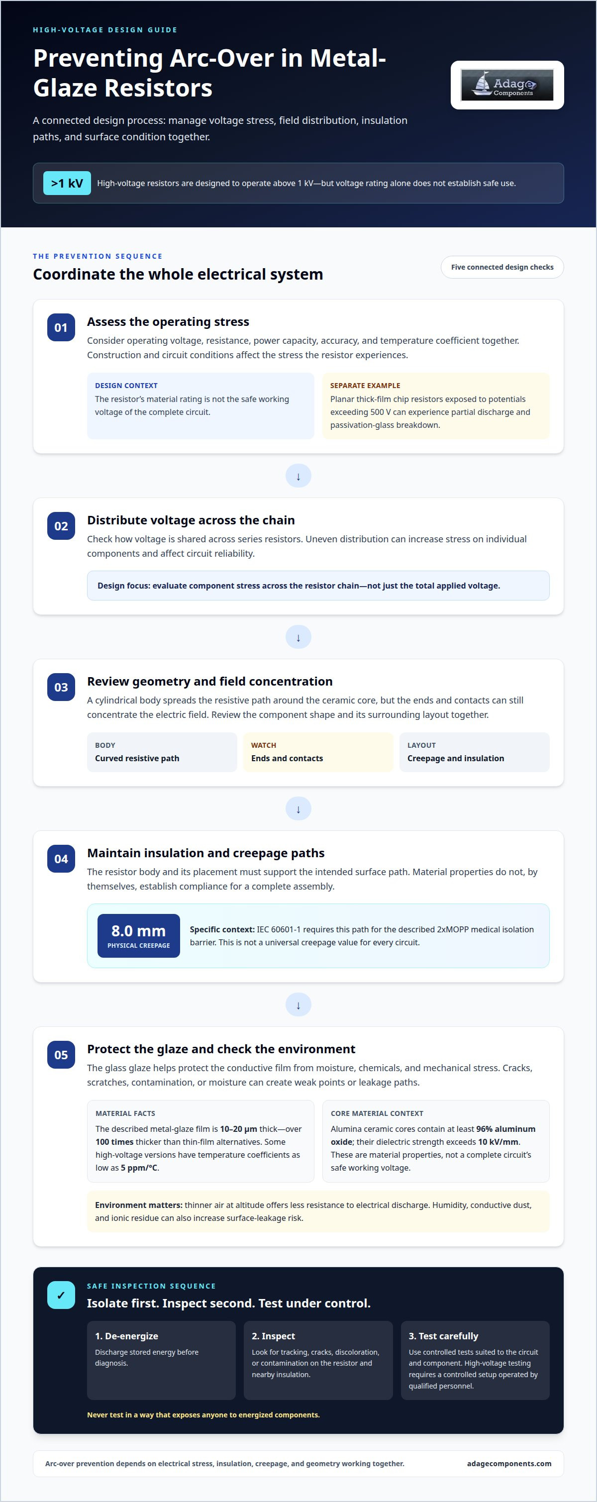
Arc-over prevention depends on more than a resistor’s voltage rating. High-voltage resistors are designed to operate above 1 kV, and high voltage metal glaze resistor arc-over prevention also relies on managing electrical stress, insulation, creepage distance, and component geometry together.
Metal-glaze resistors use a resistive film made from metal particles and glass powder on a ceramic substrate. Their construction can suit high-voltage applications, but limiting arc-over risk depends on both the resistor’s operating limits and the surrounding layout. This guide explains how to assess voltage stress, resistor chains, insulation, and geometry. It also shows why creepage paths and even voltage distribution matter when selecting a resistor for a high-voltage circuit.
Key Takeaways
- Understand how a metal-glaze resistor’s cylindrical form influences electric-field distribution and arc-over risk.
- Learn how the glass layer protects the conductive film and supports reliable resistor operation.
- Assess operating limits by considering voltage, resistance, power capacity, accuracy, and temperature coefficient together.
- See how voltage sharing across a resistor chain affects component stress and circuit reliability.
- Identify how insulation, creepage paths, and geometry contribute to preventing arcing in high-voltage designs.
What Are Metal Glaze Resistors?
Metal-glaze resistors are made by firing metal particles and glass powder onto a ceramic substrate to form a resistive film. Arc-over occurs when electrical stress causes a discharge across the resistor surface or through inadequate insulation. High voltage metal glaze resistor arc-over prevention therefore depends on managing the electric field, surface paths, and insulation together.
Cylindrical Geometry and Field Distribution
A cylindrical resistor’s geometry affects how electrical potential is distributed along its surface. The curved body spreads the resistive path around the ceramic core, but the ends and contacts can still concentrate the electric field. Localized stress can encourage surface discharge, particularly when creepage distance or surrounding insulation is inadequate. Consider geometry alongside voltage and layout: high voltage metal glaze resistor arc-over prevention depends on how these factors interact.
Electrical Characteristics
Metal-glaze resistors use a cermet film that combines conductive metal with glass, providing a stable resistance path. The described film layer is 10 to 20 μm thick, over 100 times thicker than thin-film alternatives. Some high-voltage versions have temperature coefficients as low as 5 ppm/°C. These characteristics matter in precision applications where resistance stability, electrical noise, and temperature variation affect circuit performance.
Continuous electrical stress can cause resistance drift, localized heating, insulation breakdown, or surface tracking. Planar thick-film chip resistors exposed to potentials exceeding 500 V can experience partial discharge, passivation-glass breakdown, and premature failure. In a metal-glaze part, damage to the resistive coating or insulation can also create a path for discharge. Operating conditions and construction therefore matter together.
The ceramic core and coating contribute to insulation performance, but their properties are not interchangeable. Alumina ceramic cores contain at least 96% aluminum oxide, and their dielectric strength exceeds 10 kV/mm. These values describe the core material, not a complete circuit’s safe working voltage. Layout, resistor geometry, surrounding insulation, and voltage distribution also influence the electrical stress experienced in service.
Medical electrical applications require attention to barrier design, not just resistor selection. IEC 60601-1 requires an 8.0 mm physical creepage path for the described 2xMOPP medical isolation barrier. That requirement applies to the specified isolation context. The resistor’s body and its placement must support the intended path; a component’s material rating alone does not establish compliance for the full assembly.
The glass glaze helps protect the conductive layer from moisture, chemicals, and mechanical stress, reducing the risk of environmental damage such as electric corrosion. Conditions still matter: damage to the coating or surface contamination can create weak points and change electrical behavior. Assess the ceramic core, glaze integrity, and electric field as connected parts of the resistor system.
For safe diagnosis, de-energize the equipment and discharge stored energy first. Inspect the resistor and nearby insulation for tracking, cracks, discoloration, or contamination, then perform controlled electrical tests suited to the circuit and component. High-voltage testing requires an appropriately controlled setup operated by qualified personnel. A resistance change or visible surface damage may indicate stress, but never test in a way that exposes anyone to energized components.
What Is a High Voltage Resistor?
A high-voltage resistor is designed to withstand high potential while controlling or limiting current. High-voltage resistors are designed to operate above 1 kV, but their safe use depends on construction, insulation, and circuit conditions. Metal-glaze construction adds a fired glass-and-metal resistive layer to a ceramic substrate, combining a conductive path with surface protection.
The glass glaze surrounds and binds the conductive particles, helping protect the film from moisture, chemicals, and mechanical stress. This barrier supports stable operation but does not make the resistor immune to damage. Cracks, scratches, or contamination can expose the conductive layer or change the surface path. Under electrical stress, these defects can become points where leakage or discharge begins.
Passivation and moisture protection limit unwanted interaction between the resistive film and its environment. An intact glaze helps prevent moisture and chemical residues from reaching the conductive layer. In a damp enclosure, however, moisture may collect on exposed surfaces and promote leakage between regions at different potentials. Conductive dust and ionic residue can create similar tracking paths.
Altitude affects arc-over risk because thinner air offers less resistance to electrical discharge. Assess how the device’s insulation and clearances perform in its actual operating environment. A resistor that operates stably in a clean, dry enclosure may face greater surface-leakage risk where humidity, residue, and reduced air density occur together.
Clean contamination without damaging the glaze, terminals, or nearby insulation. First isolate the equipment and discharge stored energy. Use an electronics-cleaning process compatible with the assembly, then let surfaces dry fully before operation. Avoid abrasive tools that could scratch the protective layer. Apply conformal coating cleanly and only when it is compatible with the circuit’s electrical and thermal requirements. Trapped residue or voids can weaken insulation instead of improving it.
In high-voltage circuits, a resistor can limit current or establish a controlled voltage division. This role is relevant in communication equipment, voltage-measurement circuits, and medical equipment that controls high-voltage pulses. Match the operating voltage and power handling to the circuit, while maintaining adequate insulation around the component. The coating is only one part of the protection: spacing and the assembled device’s geometry also shape discharge paths.
For precision devices, temperature changes and electrical loading can shift resistance or increase stress on the film. Stable performance therefore depends on operating conditions as well as the resistor’s construction. A useful component comparison considers the application, environment, and circuit function together. The resistor component line card can help identify resistor categories for that review.
High-voltage resistor operating ranges
High-voltage resistor ratings define operating limits, but voltage alone does not establish suitability. Before selecting a component for a sensitive circuit, compare its continuous working-voltage rating with its pulse and overload ratings.
Operating Voltage Ranges
A resistor’s operating range defines the voltage it can withstand under specified conditions. High-voltage resistors are designed to operate above 1 kV, with a typical range from 1 to 90+ kV or more. That spread reflects different constructions and applications, not one interchangeable rating. Match the rating to circuit voltage, resistance values, power capacity, accuracy, and temperature coefficient.
Package ratings show why part-level details matter. A listed 0207 high-voltage metal-glaze MELF package has a maximum working voltage of 1500 VRMS and 2100 VDC. These are separate ratings with different units, so they should not be treated as identical values. Select against the circuit’s actual voltage type and operating conditions, rather than assuming one figure covers every mode.
Reliability also depends on electrical loading over time. A resistor’s power capacity and temperature coefficient affect its behavior during operation. Temperature rise can increase component stress, while unsuitable resistance or power ratings can contribute to drift or failure. For precision applications, assess these characteristics alongside maximum working voltage. A voltage rating alone does not define the full operating range.
Voltage, Pulse, and Transient Ratings
A working-voltage rating applies to sustained operation; pulse or overload ratings cover brief voltage events. These ratings address different design questions. A pulse rating does not replace the continuous rating, and a working-voltage value alone does not establish transient capability. Compare both ratings with the circuit’s steady voltage and expected surge waveform.
For the 0207 package, maximum overload voltage is 3000 Vpeak under a 1.2/50 μs surge. A 0309 package lists 6000 Vpeak under the same 1.2/50 μs surge. These figures describe the stated overload condition, not continuous operation. Pulse duration and waveform are essential context when comparing a transient with a component rating.
A circuit with steady voltage and short switching spikes faces two distinct stresses. Keep the continuous voltage within the working-voltage rating, and assess the spike against the applicable overload rating and waveform. A brief peak above the working rating is not automatically acceptable: the pulse conditions must match the basis of the rating.
Base component selection on the full operating profile. Record the maximum steady voltage, voltage type, resistance value, power demand, accuracy requirement, and temperature coefficient. Identify pulse amplitude, waveform, and duration, then compare them with the overload rating. This keeps reliability decisions grounded in the actual electrical environment rather than a headline voltage figure alone.
High-voltage resistor-chain stress conditions
A resistor chain divides voltage across multiple components, but each resistor still faces electrical and thermal stress. Reliable design depends on voltage sharing across the chain, the effect of component variation on that sharing, and the insulation separating the chain from nearby conductors.
In an ideal series chain, each resistor’s voltage share depends on its resistance. Real components have tolerances, so identical nominal values may not produce equal voltage drops. A resistor with a higher actual resistance, for example, can take a larger share of the total voltage and experience greater electrical stress, even when the chain’s overall rating appears adequate.
Resistance can also shift as temperature changes. A resistor’s temperature coefficient describes how its resistance responds to temperature, and differences between components can alter voltage distribution as the chain heats. In industrial circuits that operate for extended periods, uneven heating can compound the initial mismatch. Stable chain performance therefore depends on component values, thermal conditions, and the voltage across the complete series path.
A series arrangement can divide voltage stress across an isolation boundary. Two or three high-voltage MELF resistors connected in series can split voltage stress and creepage requirements. Placement matters: physical gaps and surface paths must work with the electrical division. The chain’s electrical design cannot be separated from the board layout.
Pulse conditions create another source of stress in a resistor chain. A fast transient may not divide across components in the same way as steady voltage, especially when component characteristics or circuit geometry differ. Assess the complete chain under both continuous operating conditions and the expected transient waveform. Individual resistor overload ratings do not automatically establish the capability of the assembled chain.
Substrate and surface conditions also matter. A ceramic substrate provides the resistor’s structural and insulating base, while contamination or chemical residue near the chain can create unwanted leakage paths. In a humid industrial enclosure, deposits between components may alter surface insulation and concentrate stress around a resistor or terminal. Review the electrical path and surrounding creepage path together.
Evaluate the chain as an assembly, not as a set of isolated ratings. Calculate each resistor’s expected voltage share using its resistance and tolerance, then account for temperature coefficient and operating conditions. Also consider insulation spacing, transient exposure, and environmental contamination. This review can reveal where a component may face disproportionate stress, helping protect stability and reduce arc-over risk across the chain.
Insulation and geometry for preventing arcing
Preventing arc-over means controlling the electric field and blocking unintended discharge paths. Resistor shape, surface creepage, air clearance, and surrounding insulation all influence how voltage stress develops around high-voltage components.
Air clearance is the shortest path through air between conductive parts; creepage is the path along an insulating surface. Both matter, but they address different discharge routes. A resistor near a grounded chassis, for example, may have limited air clearance even if its surface path appears long. Select geometry and spacing for the complete assembly, not just the resistor.
Cylindrical resistor bodies distribute the resistive path around a curved surface, while terminals and cut edges can create local field concentrations. A helical trim changes that path: it extends effective creepage by 400% to 1200% compared with flat planar cuts. This geometry can make the surface path longer within a compact component design.
Helical geometry helps only when the trim is consistent along the resistor. Uniform pitch prevents localized voltage drops between adjacent turns and keeps the potential between grooves below the dielectric breakdown strength of air and epoxy overcoats. Uneven pitch can create a local stress point, so consider trim geometry together with the applied voltage distribution.
Insulation materials and physical layout provide complementary protection. A ceramic body supplies insulation and thermal resistance, while external barriers separate conductors from nearby surfaces. Moisture, dust, and chemical residue can affect surface insulation and encourage leakage paths. Design the enclosure to limit contamination and preserve intended spacing around terminals and resistor bodies.
A series design can distribute voltage across multiple components, but spacing must account for each resistor and the full chain length. Two or three high-voltage MELF resistors across an isolation boundary can split voltage stress and creepage requirements. The board layout must preserve separation between each component, conductive traces, and nearby grounded structures.
Thermal dissipation can also affect insulation performance. Heat from nearby components and restricted airflow can raise local temperatures. Position heat-generating devices so their dissipation does not compromise nearby insulation or coatings. In measurement circuits, preserve clear separation around high-impedance nodes to limit unintended leakage and protect signal accuracy.
Review the component outline, trim pattern, terminal spacing, board geometry, and environmental exposure as one design. This helps identify where field concentration or contamination could create an arc path. To compare resistor types for a design review, explore the resistor component line card.
Adage Components: Resistor distributor
Adage Components helps OEMs and EMS providers source authentic components through vetted manufacturers and partner suppliers, many franchised by top 100 distributors. Our resistor range includes Thick Film Chip Resistors, Thin Film Precision Resistors, and Carbon Film Resistors. We support commercial and automotive grade component requirements, with quality processes aligned to applicable ISO certifications.
For procurement teams managing cost and continuity, our manufacturer pricing and OEM pricing deliver one of the best costs in the industry. An international logistics program, a growing state-of-the-art warehouse, and short lead times support supply planning and integration with your MRP system, helping products arrive at your facility on time.
Contact Adage Components to discuss resistor sourcing for your requirements.
Put Your Resistor Selection Into Action
Turn the design criteria into a sourcing plan by matching component requirements to the application and procurement schedule. This is a practical next step for high voltage metal glaze resistor arc-over prevention: keep electrical design decisions connected to the resistor types needed for production.
Adage Components supplies Thick Film Chip Resistors, Thin Film Precision Resistors, and Carbon Film Resistors. These categories give procurement teams a starting point for matching resistor requirements to the BOM and design.
Bring resistor requirements and sourcing priorities together, then review the relevant component categories. A clear specification helps focus the procurement decision and maintain continuity between engineering and purchasing.
Get manufacturer pricing on resistor options from Adage Components and take the next step toward a well-defined sourcing plan.
Frequently Asked Questions
What voltage and power ratings apply to metal glaze resistors?
Voltage and power ratings are separate limits, and both must suit the circuit’s operating conditions. High-voltage resistor ranges can extend from 1 kV to 90+ kV or more, while package ratings vary. For example, a listed 0207 high-voltage metal-glaze MELF has working-voltage ratings of 1500 VRMS and 2100 VDC. Power capability depends on the specific component and thermal conditions, so assess it separately.
How do creepage distance and clearance affect resistor arc-over prevention?
Clearance is the shortest path through air between conductive parts; creepage follows an insulating surface. Both influence where a discharge could travel, but contamination affects surface paths differently from air paths. Residue on a board, for example, can compromise creepage even when the air gap is unchanged. Assess the complete assembly, including nearby conductors, insulation surfaces, and environmental exposure, rather than relying on component spacing alone.
What resistor spacing is recommended for high-voltage PCB layouts?
There is no single spacing value that applies to every high-voltage PCB. The layout must account for working voltage, insulation purpose, surface conditions, and the required creepage and clearance paths. For a medical isolation design, the described 2xMOPP barrier requires an 8.0 mm physical creepage path under IEC 60601-1. That specific figure does not automatically apply to other circuit types or insulation arrangements.
When should series resistor strings be used instead of a single resistor?
Use a series string when the design needs to divide voltage stress across multiple components or create a longer physical path across an isolation boundary. Two or three high-voltage MELF resistors can be connected in series for this purpose. The string distributes voltage across its components rather than placing the full electrical demand on one resistor. Account for resistance tolerances and unequal voltage sharing in the design.
What standards govern insulation and creepage for high-voltage resistors?
The applicable standard depends on the component and end-use context. IEC 60115-8 governs fixed surface-mount power resistors. IEC 60601-1 addresses medical electrical equipment; the described 2xMOPP isolation barrier requires an 8.0 mm physical creepage path. These standards cover different scopes, so use the one relevant to the resistor’s role and the equipment’s insulation design. A component standard alone does not establish system-level compliance.
What are common failure risks and warning signs of resistor surface tracking?
Surface tracking can develop when contamination, moisture, or insulation damage creates a conductive path across a resistor or nearby board surface. Warning signs include dark tracks, discoloration, cracks, residue, or resistance drift. A conductive deposit between a resistor terminal and an adjacent trace, for example, may cause leakage. De-energize equipment before inspection; qualified personnel should investigate suspected damage using controlled methods.
Disclaimer
Cross-referenced components needs to be confirmed by the client with either spec. sheet or samples or both.
Please note, we use AI to help us, information is verified to be correct but we can not guarantee 100% accuracy.


