

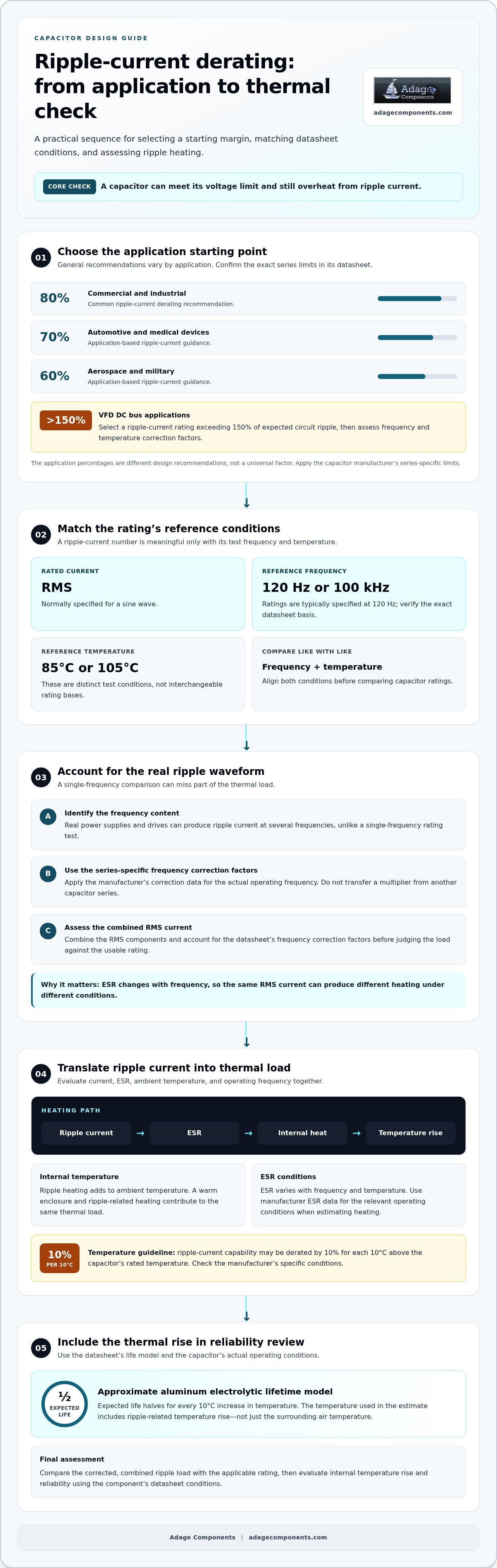
A capacitor can meet its voltage limit and still face excessive ripple-current heating. For general commercial and industrial designs, aluminum electrolytic capacitor ripple current derating is commonly set at 80% of the rated ripple-current capacity. When ripple contains multiple frequencies, assess the combined RMS current and apply the datasheet’s frequency correction factors before judging the load.
That distinction matters because ripple-current ratings are specified under reference conditions, while a real power supply or drive can produce current at several frequencies. A single-frequency comparison may therefore miss part of the thermal load.
This article explains capacitor derating, how ripple-current ratings relate to their reference conditions, and how to combine multiple-frequency components using RMS. It also connects ripple-current heating to capacitor reliability, helping you assess electrical load and its thermal effects together.
Key Takeaways
- Derating creates operating margin against voltage stress and heat, but the right margin depends on the capacitor’s conditions of use.
- Read ripple-current ratings alongside their reference frequency and temperature; a rating alone may not reflect circuit conditions.
- For ripple at multiple frequencies, combine the RMS components and account for the datasheet’s frequency correction factors.
- Ripple current produces heat through the capacitor’s ESR, so evaluate internal temperature rise when considering reliability.
- Use the resulting thermal and electrical assessment to compare capacitor choices and understand where the design has limited margin.
What Is Capacitor Derating?
Capacitor derating means operating below a component’s rated limits to reduce electrical and thermal stress. For an aluminum electrolytic capacitor, assess voltage, ripple current, ambient temperature, and operating frequency together.
Ripple Heating and Internal Temperature Rise
Ripple current generates internal heat as it flows through the capacitor’s equivalent series resistance (ESR). This temperature rise adds to ambient temperature, so the capacitor’s internal operating temperature can exceed the surrounding air temperature. For example, a capacitor in a warm enclosure faces both elevated ambient heat and additional ripple-related heating. This combined thermal load matters because component ratings are based on defined operating conditions.
Temperature Effects on Capacitor Lifetime
An approximate aluminum electrolytic capacitor lifetime model halves expected life for every 10 °C increase in ambient temperature. The temperature used in a life estimate also includes the rise caused by ripple current, not just the air temperature around the component. A capacitor operating with substantial ripple can therefore run hotter than its environment suggests. Use the datasheet’s life model and operating conditions to assess the effect.
ESR Changes with Frequency and Temperature
ESR varies with frequency and temperature, changing how much heat a given ripple current produces. In aluminum electrolytic capacitors, ESR generally decreases as frequency rises, which can allow greater ripple current at higher frequencies. Temperature also affects ESR, so a value measured under one operating condition may not apply under another. Use the manufacturer’s ESR data for the relevant frequency and temperature when estimating heating.
Voltage derating provides another margin against continuous electrical stress. A general recommendation is to operate aluminum electrolytic capacitors at no more than 80% of rated voltage. Under that rule, a 50 V-rated capacitor should not operate above 40 VDC continuously. For continuous operation at 300 VDC, the corresponding recommendation is a capacitor rated for at least 375 V. These are design recommendations, not replacements for the component’s datasheet limits.
Temperature can also reduce usable ripple-current capacity. A general guideline derates ripple-current capability by 10% for each 10°C above the capacitor’s rated temperature. Some manufacturers recommend voltage derating when capacitors operate above 85 °C. Apply the specific manufacturer’s conditions because construction and rated temperature affect the appropriate margin.
For a surface-mount or radial-lead capacitor, a rated-voltage endurance estimate can include the factor 2 raised to the ambient-temperature difference divided by 10°C. When endurance testing includes rated ripple current, the estimate also accounts for the difference in ripple-related temperature rise, using 5°C in the exponent. These relationships show why voltage, ambient temperature, and ripple heating belong in the same derating assessment.
Aluminum electrolytic ripple-current rating reference conditions
A ripple-current rating is meaningful only alongside its test frequency and temperature. These reference conditions determine how closely the published value matches the capacitor’s actual application.
Aluminum electrolytic ripple-current ratings are normally RMS values for a sine wave at 120Hz or 100kHz. Ratings are typically specified at a reference frequency of 120 Hz and a reference temperature of 85°C or 105°C. These are distinct reference conditions, so identify the exact rating basis in the datasheet rather than treating every listed current as interchangeable.
Frequency matters because ESR changes with frequency, affecting heat generated by the same RMS current. If a capacitor is rated at 120 Hz but operates in a switching circuit, its current waveform and frequency content may differ substantially from the rating test. Apply the datasheet frequency correction factor to the 120 Hz rating, using the actual operating frequency. The temperature reference matters too: a 105°C rating and an 85°C rating do not represent identical test conditions.
Manufacturer Derating Guideline Differences
Manufacturers can set different ripple-current guidance because capacitor series, reference conditions, and intended applications differ. Compare the precise series datasheet, including its rated frequency, temperature, and correction factors; the same nominal capacitance does not make ratings directly comparable. Application-based recommendations also vary: general commercial and industrial guidance uses 80%, while automotive and medical-device guidance uses 70%, and aerospace and military guidance uses 60%.
For an apples-to-apples comparison, first align the rated frequency and reference temperature. Then account for actual operating conditions using the correction data for the relevant series. Do not transfer a frequency multiplier from one series to another. Even within a product family, the specified ripple-current rating may depend on operating temperature and measurement conditions. These details significantly affect the usable current in a design.
Choosing a Derating Factor
Use the application-specific recommendation as a starting point, then apply the capacitor manufacturer’s series-specific limits. The general commercial and industrial recommendation is 80%; automotive and medical-device recommendations are 70%, while aerospace and military guidance is 60%. For VFD DC bus applications, select a rating exceeding 150% of expected circuit ripple, then assess frequency and temperature correction factors.
These percentages describe different design recommendations, not a universal rating for every aluminum electrolytic capacitor. A commercial design may use the 80% guideline, while a VFD DC bus design has the separate recommendation to exceed 150% of expected ripple. Keep the distinction clear: one is a derating guideline, and the other sets a rating above anticipated circuit ripple. The datasheet’s conditions govern the final comparison.
Once the required rating and reference conditions are clear, compare suitable capacitor options against the circuit’s actual needs. A relevant capacitor component line card can help organize that selection.
RMS conversion for ripple currents at multiple frequencies
A capacitor’s ripple load may combine switching current, harmonics, and lower-frequency components. Assess the complete current waveform, not just its largest frequency component.
Combining Currents Across Frequencies
For distinct frequency components, calculate the combined RMS current as the square root of the sum of their squared RMS values. This provides a single current measure for evaluating the capacitor’s total ripple load. First, measure or simulate the current waveform through the capacitor under actual operating conditions. Then identify its frequency components and calculate the RMS value of each.
RMS Ripple Current and Peak Current
RMS current represents the equivalent heating effect, while peak current is the waveform’s maximum instantaneous magnitude. Capacitor ripple-current ratings are RMS values, so comparing a peak reading directly with that rating gives the wrong basis. For a pure sine wave, peak current equals √2 times RMS current; complex waveforms need their own RMS calculation.
For a waveform sampled over time, RMS is the square root of the mean of the squared current samples. This time-domain method includes all components captured in the waveform. Alternatively, separate the frequency components and combine them using the root-sum-square calculation. The methods should agree when the measurement accurately captures the relevant signal.
In drives and switching power supplies, ripple commonly appears at 4-20 kHz and its harmonics. A circuit can also contain lower-frequency ripple. A single reading at the switching frequency may therefore omit current carried at other frequencies. Use a current measurement in series with the capacitor, or simulate the capacitor branch, then calculate RMS across the full operating waveform.
Current RMS alone does not fully describe heating when equivalent series resistance changes with frequency. For each component, calculate its contribution as current squared multiplied by ESR at that frequency. Add those heating contributions, then compare them with the reference condition. For example, equate the sum of I² × ESR(f) terms to I² × ESR at 120 Hz. This translates mixed-frequency loading into a heating-equivalent reference current.
The aluminum electrolytic capacitor ripple current derating calculation must preserve the rating’s stated frequency baseline. A frequency-conversion example may define multipliers relative to rated ripple current at 100 Hz; retain that baseline. Don’t apply a multiplier as though it were measured current. Adjust the allowable rating for each component’s frequency, then assess whether the combined thermal load stays within the capacitor’s applicable limit. This frequency-aware approach is central to aluminum electrolytic capacitor ripple current derating in circuits with mixed ripple components.
Ripple-current heating and capacitor reliability
Ripple current affects reliability by generating heat in the capacitor’s equivalent series resistance (ESR). The resulting temperature rise adds to the thermal load during continuous operation. A capacitor’s ripple-current rating therefore matters beyond electrical performance: excessive heating can shorten expected service life and increase the risk of premature failure.
The heating mechanism follows I²R losses: current squared is multiplied by ESR, so higher ripple current can sharply increase power dissipation. For current components at different frequencies, ESR varies. Calculate heating from each component’s current and corresponding ESR rather than treating all components as if they share one resistance. The total heat load helps establish the expected internal temperature rise.
For lifetime estimates, use the capacitor’s actual operating temperature, not ambient temperature alone. The calculation defines operating temperature as actual ambient temperature plus the rise caused by ripple current. If ambient temperature is below 40°C, the ripple-current lifetime calculation uses 40°C as the ambient value. This floor prevents an artificially low ambient reading from understating the thermal conditions used in that estimate.
A practical assessment connects three values: ambient temperature, ripple-related temperature rise, and the datasheet’s endurance conditions. For example, a capacitor in a control cabinet may experience cabinet heat as well as its own ripple heating. The combined temperature determines how closely operation matches the rated endurance conditions. Evaluating only room or cabinet temperature misses the heat produced inside the component.
Rated lifetime figures apply under stated conditions, not every operating profile. Aluminum electrolytic capacitors commonly have typical lifetimes from 2,000 to 10,000 hours at rated conditions. One life-estimation example uses a 105 ℃ rating and a 2000-hour guarantee, then estimates 32000 hours at a use temperature of 65 ℃. Treat those figures as tied to that example’s calculation conditions, not as a universal prediction for every series.
Use the following reliability review for continuous operation:
- Determine RMS ripple current across the operating waveform and its frequency components.
- Use ESR values corresponding to those frequencies to estimate I²R heating.
- Add the calculated ripple-related rise to actual ambient temperature.
- Compare the resulting operating temperature with the datasheet’s endurance conditions.
This process connects ripple-current ratings with thermal stress and expected life. If the estimated internal temperature exceeds the design target, reduce ripple loading or select a capacitor with more suitable rated capacity and endurance conditions.
Aluminum electrolytic capacitor ripple current
Ripple-current capability depends on frequency because equivalent series resistance (ESR) changes with frequency. As frequency rises, ESR generally falls, allowing higher ripple current for the same heating effect. However, that does not mean every switching waveform automatically supports higher current. The applicable frequency correction factor, operating temperature, and specified rating conditions determine the usable limit.
For a 120 Hz rating, the frequency correction factor is 1.0. At 1 kHz, the factor is 1.2 - 1.5; at 10 kHz, it is 1.3 - 1.8. At 100 kHz, it is 1.3 - 2.0. These ranges illustrate why frequency matters, but they are not a substitute for the specific capacitor series datasheet.
Use the correction factor to adjust the ripple-current rating from its stated reference frequency. For example, a design using a capacitor rated at 120 Hz must account for the actual operating frequency before comparing circuit ripple against the corrected allowable current. The manufacturer’s specified factor applies to its stated conditions. Don’t transfer a factor between series or assume the maximum value applies across all operating temperatures.
Switching supplies and drives often produce a fundamental switching component along with harmonics. Each component can encounter a different ESR, so frequency-specific heating matters as well as total RMS current. Assess a filtering capacitor exposed to switching ripple using the actual waveform or a simulation of current through the capacitor. A single-frequency estimate may overlook energy carried by other components.
For each capacitor option, organize the assessment around these design inputs:
- Identify the rated ripple current and its reference frequency and temperature.
- Determine the ripple-current components present during continuous operation.
- Apply the series-specific frequency factors to the rated current.
- Account for operating temperature when comparing calculated load with allowable capacity.
Frequency correction supports a thermal comparison; it does not change the capacitor’s dielectric, voltage rating, or lifetime specification. The ripple-current rating must still meet the circuit’s continuous load under actual conditions. If calculated demand approaches the corrected limit, consider a capacitor with greater specified ripple capability or a design that shares current across components. The choice should meet both filtering needs and thermal limits.
Compare capacitor options against your circuit’s frequency profile and operating-temperature requirements using the capacitor component line card.
Adage Components: Thick Film Chip Resistors
Adage Components offers Thick Film Chip Resistors for OEM and EMS sourcing requirements. Direct, verified procurement channels support authentic components, cost-effective sourcing, and manufacturer pricing. Customers can access the advantages associated with tier-one distributors at OEM pricing.
When sourcing plans require a coordinated supply approach, Adage Components supports international logistics and global stocking programs. Shorter-than-average lead times and manufacturing audits help align component sourcing with quality and delivery requirements. The offering also includes Thin Film Precision Resistors, Carbon Film Resistors, and MELF Resistors.
Review the component options for your procurement needs, and contact Adage Components or visit adagecomponents.com to discuss your requirements.
Carry the Calculation into Component Selection
Use the analysis as a design input, not a spreadsheet endpoint. Record the measurement method, operating profile, selected series, and assumptions alongside the component requirement. This gives engineering and procurement a shared basis for reviewing substitutions, lifecycle planning, and supply continuity as designs move from prototype to production.
A disciplined approach to aluminum electrolytic capacitor ripple current derating keeps the decision tied to the application, rather than an isolated catalog figure. As requirements change, document the updated operating profile and reassess the component choice before approving a replacement. This makes decisions traceable across design revisions and sourcing cycles.
Adage Components supports component sourcing for OEM and EMS requirements. Review relevant categories through the Adage Components line card, and align your next sourcing step with your design requirements. Clear criteria help keep technical priorities visible during procurement and provide a strong starting point for the next design decision.
Frequently Asked Questions
How is ripple current rated for aluminum electrolytic capacitors?
It is rated as an RMS current under stated frequency and temperature conditions. The datasheet gives the value in amperes RMS, not peak amperes. Before comparing a circuit value, identify the rating’s reference frequency and temperature, then account for the operating waveform. For instance, a pulsed current trace can have a peak far above its RMS value, so compare its calculated RMS load with the RMS rating.
How do temperature and frequency affect aluminum electrolytic capacitor ripple current ratings?
Higher frequency generally reduces aluminum electrolytic capacitor ESR, while higher operating temperature changes the allowable ripple load and thermal margin. Use the frequency correction factor and temperature limits for the exact capacitor series. For example, listed factors are 1.2 - 1.5 at 1 kHz and 1.3 - 2.0 at 100 kHz. These ranges illustrate variation; the applicable datasheet value governs selection.
How do manufacturers calculate allowable ripple current from capacitor temperature rise?
Manufacturers relate ripple heating to current squared and ESR, then assess the resulting temperature rise against specified operating limits. A useful comparison is the heating-equivalence relationship: operating-frequency current squared multiplied by ESR at that frequency equals reference current squared multiplied by ESR at the reference frequency. Manufacturers use series-specific data and test conditions, so the allowable current depends on the capacitor’s construction and rating basis.
How does ripple current affect aluminum electrolytic capacitor lifetime?
Ripple current adds internal heat, which can raise the capacitor’s operating temperature and reduce expected lifetime. For a useful estimate, combine measured ambient temperature with ripple-related temperature rise, then apply the capacitor’s endurance model. A 5,000-hour endurance rating at 85°C corresponds to approximately 10,000 hours at 75°C in the provided example. Treat that comparison as an estimate under its stated model, not a guaranteed service life.
How does ESR and self-heating determine ripple current limits in aluminum electrolytic capacitors?
ESR converts ripple current into heat through I²R losses, so the limit depends on both current and resistance at each frequency. For a mixed-frequency waveform, calculate each component’s heating contribution using its corresponding ESR, then combine the contributions. This is more informative than comparing total RMS current against a single ESR value when switching ripple and lower-frequency components both flow through the capacitor.
What are the risks of exceeding an aluminum electrolytic capacitor's ripple current rating?
Exceeding the rating can raise internal heating beyond the capacitor’s specified operating conditions. This extra thermal stress can shorten expected lifetime and contribute to premature failure, particularly during continuous operation. Compare the rating with frequency correction and operating temperature in mind, not just nominal RMS current. A design review can then identify whether the load exceeds the component’s corrected capacity or endurance conditions.
Disclaimer
Cross-referenced components needs to be confirmed by the client with either spec. sheet or samples or both.
Please note, we use AI to help us, information is verified to be correct but we can not guarantee 100% accuracy.


