

A lower-ESR tantalum capacitor isn’t automatically the safer choice for a power supply. Reliable selection depends on checking voltage margin separately from ripple-related heating, rather than relying on one generic derating rule. That’s the core of tantalum capacitor ESR derating in power supplies.
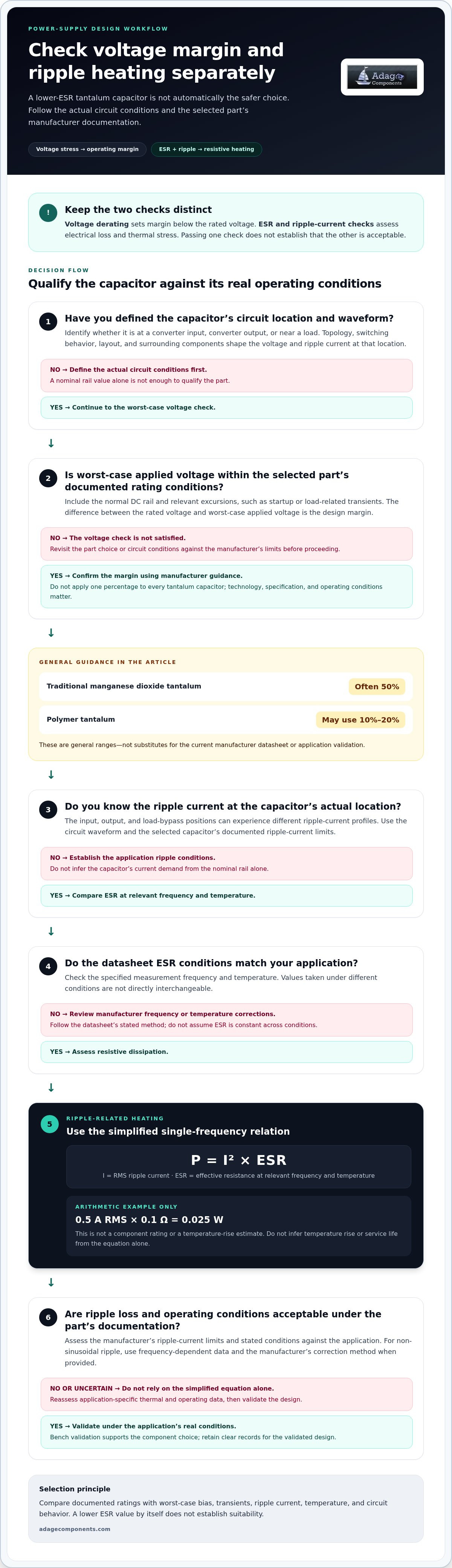
If you’re unsure how a capacitor’s voltage rating, ESR, and ripple-current limit translate into circuit requirements, the answer depends on the part and its operating conditions. Derating guidance varies by tantalum technology: traditional manganese dioxide parts are often associated with 50% voltage derating, while polymer types may use 10% to 20%. These are general ranges, not substitutes for the current manufacturer datasheet or application validation.
This guide explains how operating voltage establishes margin, while ESR and ripple current determine whether heating and performance remain acceptable under real conditions. You’ll learn which datasheet parameters to compare, how temperature and circuit behavior affect selection, and how to set application-specific margins. The result is a defensible component choice, supported by validation and clear sourcing records.
Key Takeaways
- Assess voltage margin separately from ESR and ripple-related heating. One derating rule doesn’t cover every risk in tantalum capacitor ESR derating in power supplies.
- Use the datasheet’s ESR measurement conditions and ripple-current limits to assess heat dissipation at your operating temperature and under your circuit conditions.
- Compare solid, polymer, and wet tantalum options using documented ratings and application constraints, not assumptions about an entire technology.
- Build a selection workflow around worst-case bias, transients, ripple current, temperature, lifetime needs, and bench validation.
- Protect a validated design with traceable part identification and documented sourcing for the approved component.
Why Tantalum Capacitor ESR Derating Matters in Power Supplies
A power-supply capacitor must meet electrical demands without exceeding its documented limits. A part can have adequate capacitance and a rated voltage above the nominal rail, yet still be unsuitable if circuit transients, ripple, temperature, or ESR fall outside the manufacturer’s specified conditions. Evaluate each requirement separately.
Equivalent series resistance (ESR) is the resistive component of a capacitor’s equivalent series impedance under stated measurement conditions, such as frequency and temperature. It contributes to ripple voltage and internal power dissipation, but it isn’t the only factor. Capacitance and equivalent series inductance (ESL) also affect behavior across frequency. The Tantalum Capacitor Overview provides background on capacitor construction and characteristics. For design limits, use the selected part’s current manufacturer documentation.
What does voltage derating mean for a tantalum capacitor?
Voltage derating means operating a capacitor below its rated voltage. The rating is a manufacturer-defined limit under stated conditions; the circuit’s actual voltage is what the component experiences in operation. That includes the normal DC rail and relevant excursions, such as startup or load-related transients. The difference between the rating and the worst-case applied voltage is the design margin.
Derating is the practice of operating a component within manufacturer limits with margin for the conditions the design expects. That margin is a design measure, not a guarantee of reliability or service life. Required margin depends on the capacitor technology, part specification, circuit conditions, and manufacturer guidance. Don’t apply one percentage to every tantalum capacitor. Review the selected manufacturer’s datasheet and application guidance, including any conditions attached to its voltage rating.
Why does ESR matter in a power-supply capacitor?
ESR affects how a capacitor responds to changing current. In a power supply, ripple current through ESR contributes to an in-phase ripple-voltage component and causes resistive heating. Lower ESR may help in one design, but it isn’t automatically the right choice. Circuit stability, ripple behavior, current profile, and component limits all matter. Evaluate the specified ESR at conditions relevant to the application instead of treating one value as universal.
Keep the electrical quantities distinct. Capacitance describes charge storage; rated voltage sets a documented operating limit; ESR represents resistive impedance; and ESL represents inductive impedance. They influence different aspects of circuit behavior and aren’t interchangeable selection criteria.
Location and topology shape the requirement. A capacitor at a converter input may face a different ripple-current profile from one at the output or near a load. Switching behavior, layout, and surrounding components also affect the voltage waveform at the capacitor. For tantalum capacitor ESR derating in power supplies, define the actual circuit conditions first, then compare them with the manufacturer’s limits. A nominal rail value alone isn’t enough to qualify the part.
How Voltage, ESR, and Ripple Current Interact
Voltage stress and ripple-related heating are separate design checks. A capacitor can operate below its rated voltage and still dissipate too much heat under ripple current. Conversely, acceptable heating doesn’t establish that the applied DC voltage or transients are within the part’s voltage limits. Voltage derating sets operating margin; ESR and ripple-current checks assess electrical loss and thermal stress.
Start with the waveform at the capacitor’s actual circuit location. A converter input capacitor, output capacitor, and load-bypass capacitor can experience different ripple currents because their positions and functions differ. Circuit topology, switching behavior, layout, and other components shape the current the selected capacitor must handle.
How does ESR contribute to ripple and capacitor heating?
For a simplified single-frequency case, resistive dissipation is P = I² × ESR, where I is the RMS ripple current and ESR is the effective resistance at the relevant frequency and temperature. For illustration only, 0.5 A RMS through 0.1 Ω of ESR gives 0.025 W. This arithmetic example isn’t a component rating or a temperature-rise estimate.
Actual ripple current depends on the circuit and capacitor placement. Don’t infer temperature rise or service life from the equation alone. Those outcomes require application-specific thermal and operating data.
How do temperature and frequency affect datasheet interpretation?
ESR and ripple ratings are meaningful only with their stated measurement conditions. A value measured at one frequency or temperature isn’t directly interchangeable with a value measured at another. Review the manufacturer’s test conditions and any frequency or temperature correction factors in the specific datasheet before comparing your circuit conditions with its limits.
For non-sinusoidal ripple, one ESR value may not represent losses across the waveform’s full frequency content. Where the manufacturer provides frequency-dependent data, assess the relevant components of the ripple spectrum using those values. If the datasheet specifies a correction method, follow it rather than assuming a constant ESR or applying a factor from another capacitor family.
Temperature also affects the operating assessment. Compare expected ambient and local operating conditions with the datasheet’s temperature range and ripple guidance. Include the capacitor’s installation environment and nearby heat sources in the design review. Bench measurements on a representative assembly can help validate predicted operating conditions, but they don’t replace the manufacturer’s limits.
- Voltage check: Compare the maximum DC voltage, including relevant transients, with the part’s rated-voltage guidance.
- Ripple check: Determine the RMS ripple current at the capacitor location and assess ESR-related dissipation under specified conditions.
- Thermal check: Evaluate the operating temperature and any datasheet correction factors, then validate the design under representative conditions.
This two-track method makes tantalum capacitor ESR derating in power supplies a circuit-level decision rather than a single-percentage rule. Once the electrical requirements are defined, Adage Components’ tantalum capacitor line card can support sourcing for a qualified design.
Compare Tantalum Capacitor Options Without Assuming One ESR Rule
“Solid,” “polymer,” and “wet” describe broad tantalum capacitor construction categories, not complete electrical specifications. Parts within a category can differ in rated voltage, capacitance, ESR, ripple capability, temperature range, and intended operating conditions. Compare manufacturer datasheets, not category labels alone. The matrix below identifies what to check without assigning one set of limits to every construction.
| Construction category | Datasheet comparison | Design implication |
|---|---|---|
| Solid tantalum | Check the specific part’s rated voltage, capacitance, ESR test frequency and temperature, ripple-current limit, operating-temperature range, and application notes. | Confirm the manufacturer’s voltage and ripple guidance for the exact part and conditions. “Solid” alone doesn’t establish an appropriate margin. |
| Polymer tantalum | Compare the same electrical parameters, including how ESR and ripple ratings are defined and any temperature-related conditions or restrictions. | Some polymer designs offer lower ESR than other tantalum constructions, but actual values and suitability remain part-specific. Check regulator requirements and manufacturer guidance. |
| Wet tantalum | Review rated voltage, capacitance, ESR conditions, ripple limits, temperature range, and any manufacturer-stated mounting or application constraints. | Use the stated conditions and limits for the specific device. Don’t transfer assumptions from solid or polymer parts. |
Solid, polymer, and wet tantalum: which differences affect selection?
Construction can influence electrical behavior and the conditions a manufacturer specifies for use, but it doesn’t replace part-level review. Compare like-for-like data: note the frequency and temperature for ESR, the conditions attached to ripple ratings, and any limits related to voltage or operating environment. If a datasheet doesn’t define a parameter under your application’s conditions, don’t treat another family’s value as a substitute.
For each candidate, map the documentation to the circuit. Confirm rated voltage against expected operating and transient stresses, capacitance against the circuit requirement, and ripple capability against the current at the component location. Then assess temperature and application constraints. This keeps tantalum capacitor ESR derating in power supplies tied to verified data rather than a blanket rule.
When can ESR affect power-supply stability or performance?
Lower ESR isn’t automatically better. Some regulator control loops specify an allowed output-capacitor ESR range, and moving outside it can affect stability or transient response. Requirements vary by topology and controller implementation. Check the regulator or controller documentation for permitted capacitance and ESR conditions, then validate the selected combination in the actual design.
Keep three checks distinct:
- Stability: Does the capacitor meet the control-loop requirements?
- Transient response: Does the output remain within the design’s limits during load changes?
- Ripple: Are voltage ripple and ripple-related dissipation acceptable under operating conditions?
A candidate passes only when its datasheet limits and circuit-level validation support the intended use. A family name or a low ESR figure by itself cannot establish suitability.
A Practical Workflow for Setting ESR and Voltage Margins
Set margins from the circuit’s worst-case conditions, then verify the selected part against its own documentation. This makes tantalum capacitor ESR derating in power supplies a traceable engineering decision rather than a rule of thumb. Keep the electrical assessment and supporting evidence together so design reviews and future substitutions have a clear reference.
Translate the power-supply requirements into capacitor criteria
Start with the application, not a capacitor category. Record the rail’s nominal and worst-case DC voltage, startup behavior, and other documented transients at the capacitor location. Determine required capacitance and ripple current from actual circuit conditions, then capture the regulator’s ESR requirements, operating-temperature range, environmental constraints, and expected service-life target.
- 1. Define the electrical envelope. Record normal and worst-case voltage, including transients relevant to the design. Identify where the capacitor sits in the circuit and the conditions that produce the highest stress.
- 2. Establish capacitance and ripple needs. Use circuit analysis or measurement to determine the required capacitance and ripple-current profile at that location. Include the waveform and operating modes that represent demanding application conditions.
- 3. Set system constraints. Document the regulator or controller’s permitted output-capacitor ESR and capacitance requirements. Capture temperature limits, environmental conditions, and expected lifetime requirements so they remain part of component qualification.
- 4. Select a specific candidate. Identify the exact manufacturer and part number, including its tantalum technology and construction. A broad family description isn’t enough to establish voltage margin, ripple capability, or ESR suitability.
- 5. Review current manufacturer guidance. Compare the design envelope with the exact part’s datasheet and application guidance. Check rated voltage, capacitance, ESR measurement conditions, ripple limits, temperature range, and any technology-specific voltage acceleration or derating guidance. Apply only the conditions and correction factors stated for that part.
- 6. Validate and document. Test a representative design under operating conditions that exercise relevant ripple, temperature, load changes, startup, and transients. Record measured results, assumptions, datasheet revision, manufacturer guidance, and approved part identification. Reassess the evidence if the part or circuit conditions change.
Engineering checklist: Verify voltage stress against the selected capacitor’s voltage guidance. Independently verify ripple current, ESR-related heating, and operating temperature against its documented limits.
Validate the chosen part against data and testing
Bench validation should confirm the application’s behavior, not replace datasheet review. Use representative operating conditions and suitable measurement methods to assess ripple and temperature, then compare transient behavior with circuit requirements. Keep the test setup and results with the qualification record. This evidence helps engineering and procurement teams identify the approved part and understand the design assumptions behind it.
Once your electrical criteria are defined, review Adage Components’ tantalum capacitor line card to support sourcing for the qualified design.
Source Qualified Tantalum Capacitors for a Validated Design
Electrical validation applies to a specific component under defined conditions. Procurement must preserve that identity as the design moves into production. A substitute with similar capacitance or voltage ratings may differ in other documented characteristics, so changes to the approved manufacturer or part number should follow engineering review.
What should procurement preserve after engineering approval?
Keep the approved manufacturer and full part number connected to the engineering record. Retain the datasheet and application guidance used for qualification, including revisions, alongside test results and design assumptions. This gives engineering and procurement a shared reference for purchasing, production planning, and proposed component changes.
- Part identity: Record the manufacturer, exact part number, and approved ordering details.
- Technical basis: Retain the relevant datasheet revision, manufacturer guidance, and qualification results.
- Change control: Route substitutions through engineering review before changing the approved bill of materials.
- Production planning: Align purchasing records and MRP data with the approved part number.
Traceable records help keep procurement aligned with the validated design. Adage Components provides quality assurance and technical support to help OEMs and EMS providers manage component requirements during sourcing.
How does Adage Components support component sourcing and continuity?
Adage Components supplies tantalum capacitors and other electronic components to OEMs and EMS providers. We offer cost-effective component alternatives and drop-in replacements for standard industry parts, with technical support to help customers align sourcing with their design requirements.
Our private-label components and direct procurement channels support cost-conscious purchasing. Adage Components also provides international logistics coordination and global stocking programs to help businesses manage component supply and lead times. These services can be integrated with your procurement planning and MRP processes.
Keep the approved part and its documentation connected through procurement so the component entering production matches the design basis. Explore Adage Components’ electronic component line card and contact our team to discuss sourcing for your qualified design.
Carry the Qualification Forward
A reliability margin isn’t a permanent property of a component choice. It remains valid only while the design operates within the conditions used to qualify it. If the power-supply operating profile, thermal environment, regulator implementation, or approved component documentation changes, review the original decision. This keeps tantalum capacitor ESR derating in power supplies aligned with the conditions the design must meet throughout its lifecycle.
Make that review part of change control. Record what changed, identify which qualification assumptions it may affect, and route the decision to the appropriate engineering and procurement owners. A clear review path helps teams distinguish routine purchasing activity from a component or application change that could affect the validated design. It also keeps future sourcing decisions grounded in current engineering requirements, rather than relying on an old approval without its context.
With your design requirements defined, take the next sourcing step. Explore Adage Components’ electronic component line card and contact our team to move your qualified design forward.
Frequently Asked Questions
How much should you derate a tantalum capacitor in a power supply?
There isn’t one percentage that applies to every tantalum capacitor or power supply. Set the operating-voltage margin using the exact part’s datasheet and manufacturer application guidance, considering the capacitor’s construction and the circuit’s steady-state and transient conditions. For tantalum capacitor ESR derating in power supplies, document the selected margin and its rationale alongside the part number. Don’t treat a general rule of thumb as proof that a specific component is suitable.
Does lower ESR always improve power-supply performance?
No. Lower ESR can reduce resistive loss, but it may not meet a regulator’s output-capacitor requirements. For example, a controller may specify an ESR range as part of its stability criteria. Check the controller documentation before substituting a lower-ESR part, then evaluate the assembled supply for stability, output ripple, and load-step response. These are related checks, but passing one doesn’t establish that the other performance requirements are met.
Can a tantalum capacitor fail if its voltage rating is exceeded briefly?
Yes, a brief excursion above the rated voltage can damage a capacitor or contribute to failure, but the outcome depends on the component and the excursion. Don’t assume a short transient is harmless. Compare the transient’s peak, duration, and repetition with the selected manufacturer’s voltage and surge guidance. If the circuit can produce overshoot, capture the waveform at the capacitor terminals and address the cause or select a part qualified for those conditions.
What happens if ripple current exceeds the tantalum capacitor rating?
Excess ripple current can increase internal heating and push the capacitor beyond its documented operating limits. The risk depends on the actual waveform, frequency, temperature, and the manufacturer’s rating conditions; a single current reading may not describe the stress accurately. Determine RMS ripple at the capacitor’s location and compare it with the part-specific limit. If the application exceeds that limit, redesign or select a component whose documented capability covers the measured conditions.
How do you calculate tantalum capacitor ESR power dissipation?
For a simplified case, calculate resistive dissipation as P = IRMS2 × ESR, using RMS ripple current and ESR specified at relevant frequency and temperature conditions. For example, a measured ripple waveform needs to be reduced to its RMS value before applying the equation. If ripple contains substantial frequency components, use the manufacturer’s frequency-dependent data or stated calculation method rather than assuming one ESR value describes the entire waveform.
Is a polymer tantalum capacitor interchangeable with a solid tantalum capacitor?
No, not by default. A change in construction can affect ESR, ripple capability, voltage guidance, temperature limits, and other application conditions. Before substitution, compare the exact candidate’s datasheet with the approved part and the circuit’s requirements. Check regulator stability criteria as well as electrical ratings, and validate the replacement in the application. Treat a different construction or part number as an engineering change, even if capacitance and rated voltage appear similar.
Can tantalum capacitors be used in automotive-grade power supplies?
Yes, if the specific capacitor is documented as suitable for the application’s automotive requirements. Confirm the component’s qualification and operating limits in manufacturer documentation; a general industrial rating alone doesn’t establish automotive suitability. Review temperature, vibration, humidity, and electrical requirements for the design, and keep the approved manufacturer and part identification under change control. Validate the selected component in the intended power-supply application before release to production.
Disclaimer
Cross-referenced components needs to be confirmed by the client with either spec. sheet or samples or both.
Please note, we use AI to help us, information is verified to be correct but we can not guarantee 100% accuracy.


