

What if a diode that meets its headline current rating still overheats in your circuit? A Schottky diode’s reverse leakage current rises as junction temperature increases. That extra current can generate more heat, reinforcing the cycle and increasing failure risk. Effective Schottky diode thermal runaway prevention therefore depends on the complete electrothermal system, not a single rating.
Start with the datasheet, then compare its stated test conditions with your circuit and board. Forward voltage, reverse bias, switching behavior, ambient conditions, layout, and the thermal path all affect junction temperature. A component substitution or design change can shift those conditions, even when the replacement looks similar on paper.
This guide explains how electrothermal feedback develops and gives you a practical process for assessing operating conditions, heat removal, and validation. It also covers sourcing authentic components and procurement considerations for commercial and automotive-grade applications. Adage Components supplies Schottky diodes and supports OEM and EMS teams with component sourcing, quality assurance, and international logistics.
Key Takeaways
- Schottky diode thermal runaway prevention requires assessing the diode, circuit operating conditions, and thermal path as one system.
- Evaluate conduction and leakage losses across operating cases. Forward-voltage behavior with temperature varies by device and operating region.
- Thermal runaway isn’t inevitable. Compare expected junction temperatures under effective cooling with conditions that restrict heat removal.
- Use a repeatable workflow: define operating cases, calculate losses, estimate temperature, then validate with measurements and documented assumptions.
- Match voltage, current, package, and thermal requirements to the application and datasheet, and keep the approved component details aligned with procurement records.
What Schottky Diode Thermal Runaway Is, and When It Becomes a Risk
Schottky diode thermal runaway is a self-reinforcing rise in device temperature that can push the junction beyond its safe operating conditions. It is a possible electrothermal instability, not an inevitable feature of every Schottky diode. Risk depends on the specific device, circuit operating conditions, and how effectively heat travels from the junction into the package, board, and surrounding environment.
Ordinary heating is different. A diode dissipates power during normal operation, and its junction temperature rises until the heat flowing out balances the heat being generated. That temperature rise can be stable. Runaway becomes a concern if a temperature increase causes additional dissipation, creating still more heat faster than the thermal path can remove it. Schottky diode reverse leakage current can increase sharply with temperature, contributing to this feedback under reverse-bias conditions. The Schottky diode overview provides general background on device characteristics and thermal considerations.
What conditions can initiate Schottky diode overheating?
Start by identifying where the diode dissipates power. During forward conduction, a useful first estimate is forward voltage multiplied by forward current. Reverse bias matters too: reverse voltage across leakage current produces power, and leakage can rise as the junction warms. The exact behavior depends on the diode and operating point, so use relevant datasheet characteristics rather than assumed values.
Heat removal completes the picture. A compact package, limited copper area, a hot neighboring component, or poor airflow can restrict heat flow and raise junction temperature for a given power loss. These conditions don’t automatically cause runaway, but they reduce the margin between operating temperature and the device’s specified limit. Assess the selected part against the conditions stated in its datasheet.
Why a headline current rating is not a complete thermal assessment
A current rating is meaningful only alongside its stated test and mounting conditions. Datasheet ratings may depend on ambient temperature, lead or case temperature, PCB copper, and the defined thermal path. The current rating alone does not show whether your board can remove the resulting heat or keep the junction within its specified operating range.
Separate the electrical question from the thermal one:
- Electrical: Does the diode meet the circuit’s voltage, current, and operating requirements?
- Thermal: Can the actual package, board layout, and environment dissipate the calculated losses?
Use the exact datasheet conditions for the selected component, then compare them with your design’s mounting and environmental conditions. Avoid generic rules of thumb. A current that appears acceptable under one specified setup may produce a different junction temperature on another board. This comparison is the starting point for disciplined Schottky diode thermal runaway prevention.
How Electrothermal Feedback Develops in a Schottky Diode
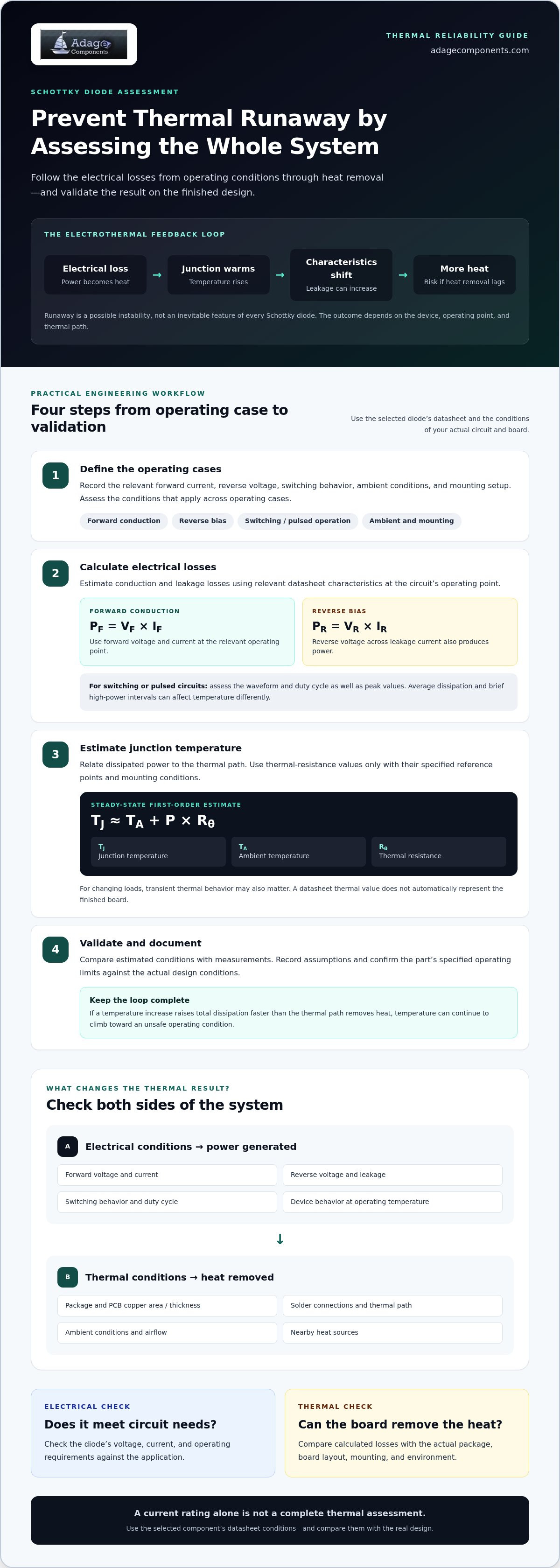
Electrothermal feedback starts when electrical power becomes heat inside the diode. That heat raises junction temperature, which can change the device’s electrical characteristics. If those changes increase power dissipation, the junction heats further. Whether the cycle stabilizes or becomes an instability depends on the diode, operating point, and ability of the package and board to carry heat away.
A useful summary is: if rising junction temperature increases the diode’s total power dissipation faster than the thermal path can remove heat, temperature can continue to climb toward an unsafe operating condition. This describes the feedback mechanism, not a universal temperature coefficient or a prediction that every Schottky diode will run away.
Forward conduction, forward voltage, and heat generation
During forward conduction, estimate instantaneous power using the operating-point relationship PF = VF × IF. For a switching or pulsed circuit, assess the waveform and duty cycle as well as peak values. Average dissipation and brief high-power intervals can affect temperature differently. Use the conditions relevant to the selected diode in its datasheet.
Forward voltage can change with temperature, but its behavior depends on the device and operating region. Don’t assume one temperature coefficient applies across all currents or Schottky diode types. Check forward-voltage values at the circuit’s actual current and temperature range, and account for how a voltage change affects dissipation at the operating current.
Junction temperature, thermal resistance, and reverse leakage
Junction temperature, often written as TJ, is the temperature of the semiconductor junction where the diode’s electrical activity occurs. Under steady-state conditions, a first-order estimate relates it to ambient temperature, dissipated power, and thermal resistance: TJ ≈ TA + P × Rθ. Use the thermal-resistance value only with its specified reference points and mounting conditions. For changing loads, transient thermal behavior may also matter.
The package, PCB copper area and thickness, solder connections, nearby heat sources, and airflow all influence the thermal path. A datasheet thermal value does not automatically represent the finished board. Confirm the assumptions behind the value, then evaluate the actual layout and enclosure.
Reverse leakage is another potential contributor. It commonly increases with junction temperature, but its magnitude and effect on total dissipation must be verified for the chosen part at the relevant reverse voltage and temperature. For Schottky diode thermal runaway prevention, include forward and reverse losses in the same thermal assessment rather than considering either in isolation.
When comparing candidate parts, use the exact electrical and thermal data for each device. Adage Components’ electronic component line card helps engineering and procurement teams identify Schottky diode sourcing options for evaluation.
Does a Schottky Diode Inevitably Run Away? Compare the Design Risks
No. A Schottky diode doesn’t inevitably enter thermal runaway. Risk depends on the selected device, electrical operating point, and circuit heat removal. A diode in a well-cooled layout may operate stably under its intended load, while the same part in a hotter, poorly cooled assembly may have less thermal margin. Schottky diode thermal runaway prevention starts with evaluating these conditions together.
Single-diode operation versus parallel Schottky devices
A single diode avoids current-sharing differences between parallel parts, but it still needs to meet the circuit’s electrical and thermal requirements. With parallel devices, small differences in forward voltage, wiring resistance, or temperature can cause unequal current. One diode may then dissipate and heat more than the others. Symmetrical connections and layout can help, while current-balancing measures may suit some designs. Choose measures and values based on the application analysis, not a generic rule.
Ambient, mounting, and operating-point comparisons
Thermal margin changes with ambient temperature and mounting. A board that spreads heat effectively in open air may perform differently inside a warm enclosure or with limited airflow. Normal load variation also differs from sustained high-current operation: brief peaks and prolonged loading impose different thermal demands. Review reverse-bias and transient conditions separately, using the device datasheet and circuit waveforms.
The comparisons below identify common mechanisms and design responses. Verify device-specific limits and behavior against the selected component’s documentation and the actual assembly.
| Condition | Risk mechanism | Design response |
|---|---|---|
| Single diode with effective heat removal | Junction temperature rises with dissipation, but the thermal path can support stable operation. | Check calculated losses and temperature against the datasheet’s stated mounting and thermal conditions. |
| Restricted airflow, elevated ambient, or limited board copper | Reduced heat transfer raises junction temperature and reduces operating margin. | Assess the assembled board and enclosure. Verify thermal assumptions for the specific package. |
| Parallel Schottky diodes | Unequal current can concentrate dissipation and heating in one device. | Review electrical and thermal symmetry. Evaluate balancing measures and their values for the application. |
| Sustained overload or fault condition | Extended current can increase dissipation beyond normal operating expectations. | Analyze credible load and fault cases, then verify device-specific limits and protection behavior. |
| Reverse bias or switching transients | Leakage or transient stress may add losses not captured by a forward-current-only assessment. | Review reverse and transient ratings alongside actual circuit waveforms. Verify relevance for the chosen part. |
This comparison helps distinguish manageable operating heat from conditions that may undermine stability. Base decisions on the complete circuit and its actual thermal environment, not on a diode rating in isolation.
A Practical Engineering Workflow to Prevent and Validate Thermal Runaway
Reliable Schottky diode thermal runaway prevention requires more than a temperature estimate. Build a traceable process from operating assumptions to calculation and bench validation. Keep predicted values separate from measurements, and document the conditions behind both. This helps engineering teams identify model uncertainty before it becomes a field reliability issue.
- Define operating cases. List normal load, startup, sustained high-current operation, credible overload or fault conditions, reverse bias, and switching transients. Record the expected ambient range, enclosure, airflow, duty cycle, and any parallel-device configuration. Prioritize cases that combine high electrical stress with restricted heat removal.
- Calculate expected losses. Use operating current and the selected diode’s datasheet forward-voltage data at relevant current and temperature conditions. Include reverse leakage losses where applicable, along with switching losses if they matter to the circuit. State waveform, duty-cycle, and temperature assumptions. Flag values that require measurement or manufacturer data.
- Estimate junction temperature. Apply the datasheet thermal information that matches the package and mounting arrangement. A thermal-resistance estimate is meaningful only when its reference points and test conditions fit the design. Account for PCB copper and heat spreading, nearby heat sources, and airflow. Compare the calculated junction temperature with the exact device limit, preserving a margin based on system requirements rather than an assumed generic threshold.
- Choose risk controls. If the estimate leaves inadequate margin, reassess diode selection, operating current, board heat spreading, and cooling. Consider circuit-level measures such as current limiting, fault protection, or thermal monitoring and shutdown where appropriate to the system. Verify that each measure addresses the relevant failure condition without introducing a new operating risk.
- Validate the design. Test representative worst-case combinations within the application’s operating envelope. Record ambient, load, airflow, board configuration, and test duration. Monitor temperature and electrical behavior with a documented method, distinguishing measured package or board temperature from inferred junction temperature. Define acceptance criteria from system requirements and the exact diode documentation.
Separate estimates from measurements
Calculations predict behavior from stated inputs; bench results describe the tested assembly and conditions. Keep both in the design record, including instrument placement, measurement method, stabilization criteria, and known uncertainty. If results diverge, investigate assumptions such as actual current waveform, thermal contact, copper geometry, or airflow before treating either value as definitive.
Reassess after design changes
A revised board, enclosure, cooling path, diode, or supplier substitution can change electrical losses or thermal performance. Recheck the relevant calculations and repeat validation when a change affects operating conditions or the component’s documented characteristics. This keeps the reliability case tied to the production configuration rather than an earlier prototype.
For component evaluation alongside this workflow, review the Schottky diode line card.
Selecting and Sourcing Schottky Diodes for Thermal Reliability
Thermal reliability starts with matching a diode to the application and checking its documented performance against the design. A part number or headline current rating isn’t enough. Review voltage and current requirements alongside package, mounting, heat dissipation, and operating conditions. Treat Schottky diode thermal runaway prevention as both an engineering selection task and a procurement control.
What to assess in a Schottky diode datasheet
Compare forward characteristics at the circuit’s operating current and temperature. Review reverse-voltage limits, leakage data, and thermal ratings under their stated test and mounting conditions. Check package details against the intended PCB design, since mounting and board construction affect heat transfer. Verify values against the exact component documentation rather than applying a generic limit across diode families.
Choose grade requirements according to the application. Commercial and automotive-grade components have different qualification contexts, and an automotive-grade requirement should align with the project’s applicable criteria. Don’t assume every Schottky diode is available in both grades or that a similar-looking part is an equivalent substitute. If a proposed replacement changes component characteristics or package, update the design review and qualification records accordingly.
Connect component quality with supply continuity
Component integrity matters throughout procurement and production. Keep the approved manufacturer and part number aligned with engineering and purchasing records, and use Adage Components’ quality assurance and manufacturing audit support as part of your sourcing process. Adage Components supplies Schottky diodes to OEM and EMS procurement teams and supports international logistics.
Keep the datasheet and approved component details connected to your MRP records so substitutions can be assessed against design requirements. For multi-component procurement reviews, the BOM submission form supports bill-of-materials cost analysis. Adage Components provides manufacturer and OEM pricing through its private-label component supply.
For a sourcing review, align the engineering-approved electrical and thermal requirements with the procurement specification. Include the exact part number, package, and applicable grade requirements to reduce ambiguity between design intent and purchasing records.
To review Adage Components’ Schottky diode sourcing options, explore Schottky diode sourcing through the line card.
Carry Thermal Reliability Through Every Design Change
Keep the reliability case connected to the production design. A new board revision, operating profile, or component substitution can change the assumptions behind an earlier thermal assessment. Treat those changes as review points so approved component data, engineering decisions, and procurement records stay aligned as the design evolves.
That discipline makes Schottky diode thermal runaway prevention an ongoing part of lifecycle management, not a one-time selection exercise. Clear records help engineering and procurement teams act on the same requirements, preserve design intent, and respond when supply conditions or product needs change.
For your next sourcing review, explore the Schottky diode options listed by Adage Components and align component selection with your application requirements. Explore Schottky diode sourcing through the line card.
Frequently Asked Questions
Can a Schottky diode enter thermal runaway under normal operating conditions?
Yes, if “normal” operation includes conditions that differ from the assumptions behind the design or rating. A load that is routine in one enclosure may create different thermal stress in a hotter installation or with altered airflow. For Schottky diode thermal runaway prevention, define normal operation using the system’s actual load profile, ambient range, and mounting conditions, then compare that case with documented device limits.
How does temperature affect Schottky diode forward voltage?
Forward voltage changes with temperature, but the direction and magnitude depend on the diode and operating point. In a circuit with a fixed load, even a modest shift may affect current or power, depending on surrounding components and control behavior. Assess the diode at the actual current range rather than extrapolating from a curve taken at a different test current. Use manufacturer data for the selected part.
Can parallel Schottky diodes share current equally?
No, equal sharing shouldn’t be assumed. A practical check is to measure or otherwise determine each branch current under the intended load, including startup or changing-load cases. If one branch carries more current, inspect trace lengths, connection resistance, device characteristics, and temperature differences before changing the design. Keep the assessment specific to the selected parts and board. A layout that shares adequately in one assembly may behave differently after a revision.
Is a heat sink enough to prevent Schottky diode thermal runaway?
No. A heat sink can help, but its effect depends on the complete path from the diode junction through the package and mounting interface to the sink and surrounding air. Poor contact, an unsuitable mounting arrangement, or obstructed airflow can limit heat transfer. Check the assembly as built, including interface materials and mechanical fit, then evaluate whether temperature and electrical behavior meet the project’s acceptance criteria.
How can engineers detect possible thermal instability during testing?
Track temperature and electrical behavior over time, not just at a single test point. Record the load, ambient conditions, airflow, and measurement location so results can be compared across runs. A temperature that keeps rising after operating conditions have stabilized, or an unexpected change in current, merits investigation. Confirm that sensor placement and method suit the package, and document how measured temperatures relate to the acceptance criteria.
Which Schottky diode specifications matter most for thermal reliability?
Prioritize the specifications that match the circuit’s stress: forward voltage at relevant current, current and reverse-voltage limits, leakage, thermal ratings, and package details. Check whether the datasheet values apply to the intended mounting and operating conditions. For procurement, preserve the exact manufacturer part number and approved datasheet with the design record. This makes engineering review more reliable if a proposed substitution arises later.
Disclaimer
Cross-referenced components needs to be confirmed by the client with either spec. sheet or samples or both.
Please note, we use AI to help us, information is verified to be correct but we can not guarantee 100% accuracy.


