

A resistor can meet the calculated resistance and still fail under a drive’s actual startup conditions. Effective anti-surge resistor selection for industrial motor drive precharge starts with the pulse, not resistance alone. DC-link capacitance, bus voltage, charging time, and restart frequency determine the electrical and thermal stress the component must withstand.
If you’re specifying a precharge resistor, limiting inrush current is only part of the job. This guide explains how to define the drive’s operating profile, compare pulse energy and power with component data, and account for thermal conditions and repeated starts. It also shows how to turn those requirements into a clear component specification for sourcing. Adage Components supports resistor sourcing and BOM cost analysis for OEMs and EMS providers. By considering cost, supply continuity, and technical requirements together, you can evaluate suitable resistor categories against your application.
Key Takeaways
- Start anti-surge resistor selection for industrial motor drive precharge with the drive’s voltage, DC-link capacitance, allowable inrush current, and charging-time target.
- Use resistance calculations as a first pass, then assess pulse energy, duration, peak voltage, tolerance, and mounting conditions.
- Keep short-duration pulse capability separate from continuous power rating. One does not establish the other.
- Include normal startup, rapid restart, fault recovery, and interrupted precharge sequences in drive validation.
- Turn approved electrical, thermal, mechanical, and documentation requirements into a sourcing-ready BOM, then assess alternatives against the full specification.
Why Industrial Motor Drives Need an Anti-Surge Precharge Resistor
At startup, an industrial motor drive must charge its DC-link capacitor bank before the inverter can use that stored energy to produce the drive’s output. If the supply is connected abruptly, the initially uncharged capacitors can draw a sharp inrush current. The precharge resistor temporarily limits that current, reducing electrical stress on the charging path while the DC link rises toward its operating voltage.
This is a startup component, not a resistor placed in series with the motor during normal operation. Once precharge is complete, a bypass path takes over so the resistor no longer carries the drive’s ordinary operating current. That distinction matters: anti-surge resistor selection for industrial motor drive precharge must address a defined transient and operating sequence, not just a continuous load.
How the motor drive precharge sequence works
In a common arrangement, the supply feeds the DC link through a precharge branch containing the resistor and a switching device, such as a relay or semiconductor switch. The DC-link capacitor charges through this restricted path. When the drive’s control sequence determines that precharge is complete, a bypass contactor closes around the resistor, establishing the main current path. The inverter then draws energy from the DC link to operate the motor.
The topology, switch arrangement, and transition conditions vary by drive design. Use the drive documentation to identify the actual current path rather than assuming every unit uses the same circuit.
The term “anti-surge” can also describe devices that address voltage transients. A surge protector provides general context on those devices, but it serves a different function from a precharge resistor. Here, the resistor limits capacitor-charging current during startup.
What the resistor must achieve at startup
The resistor has to meet three connected requirements. It must limit initial current to the circuit’s design boundary, allow the DC link to reach its required voltage within the intended startup interval, and withstand the energy converted to heat during charging. Meeting one condition does not establish that the other two are satisfied.
- Control inrush: Limit current through the precharge path and connected components during initial energization.
- Support the startup sequence: Allow the capacitor voltage to rise in time for the drive’s control system to transition to the bypass path.
- Withstand the transient: Tolerate the pulse and resulting temperature rise for the specified precharge event.
Industrial operating profiles make the last requirement especially important. A drive that starts occasionally faces a different thermal pattern from one that starts frequently or restarts rapidly. Select the resistor for the expected event and recovery conditions, not for an assumed single startup in isolation. The next step is to quantify the circuit inputs and evaluate candidate parts against them.
Calculate Resistance, Inrush Current, and Pulse Energy for Precharge
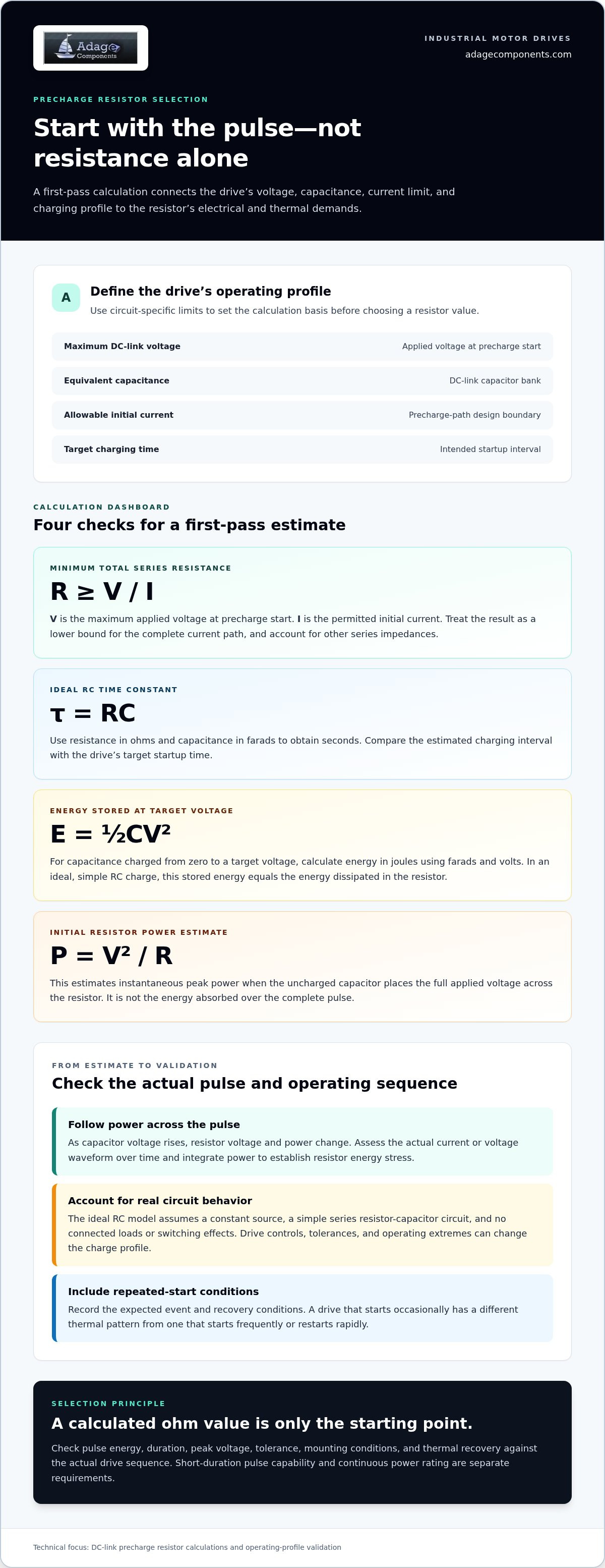
A defensible first-pass calculation begins with the drive’s operating limits, not a preferred resistor value. Record the maximum DC-link voltage, equivalent capacitance, allowable initial current, and target charging time. Use circuit-specific values from the drive design, including the actual voltage range and current boundary. These inputs establish the calculation basis for anti-surge resistor selection for industrial motor drive precharge.
Build a defensible first-pass resistance estimate
For an initially uncharged capacitor, estimate the minimum total series resistance from R ≥ V/I. Here, V is the maximum applied voltage at the start of precharge, and I is the permitted initial current. The result is a first-pass lower bound for the complete current path. Account for other series impedances when determining the resistor’s required value.
Then compare the estimated charging interval with the ideal RC time constant, τ = RC, using resistance in ohms and capacitance in farads to obtain seconds. This model assumes a constant source, a simple series resistor-capacitor circuit, and no connected loads or switching effects. Drive controls, tolerances, and operating extremes can change the charge profile, so recalculate using available limits and validate against the actual circuit. Texas Instruments’ High Voltage DC-Link Capacitor Precharge Circuit Design provides additional circuit-design context.
Calculate pulse and repeated-start loading
For capacitance charged from zero to a target voltage, the energy stored at the target is E = ½CV². Use farads and volts to calculate joules. In an ideal, simple RC charge, this stored energy equals the energy dissipated in the resistor. A real precharge circuit can differ, particularly if its switching sequence interrupts or bypasses the resistor before charging is complete.
Estimate initial resistor power with P = V²/R for the initial condition, when the uncharged capacitor places the full applied voltage across the resistor. This is an instantaneous peak estimate, not the energy absorbed over the whole pulse. As capacitor voltage rises, resistor voltage and power change. Assess the actual current or voltage waveform over the pulse and integrate power over time to establish resistor energy stress.
- Single event: Document peak current, initial power, pulse duration, and energy for the defined charge sequence.
- Repeated events: Record expected starts per unit time, then estimate average dissipation as energy per event multiplied by event frequency.
- Thermal recovery: Evaluate whether the resistor can cool between cycles under the mounting and ambient conditions in the drive.
Average dissipation does not replace the single-pulse check. Both matter: the first addresses cumulative heating, while the second captures the stress of each charge event. Keep assumptions and calculated limits with the design record, then compare candidate resistors against their datasheet pulse conditions. Adage Components’ resistor component categories can support the sourcing review once the electrical requirements are defined.
Compare Precharge Resistors Beyond the Calculated Ohm Value
A calculated resistance is a starting point, not a component approval. Two candidates with the same nominal ohmic value can differ in tolerance, pulse capability, voltage limit, thermal behavior, and mounting requirements. For anti-surge resistor selection for industrial motor drive precharge, compare each candidate with the complete startup profile and its own datasheet evidence.
Keep continuous power rating separate from short-duration pulse capability. A continuous rating describes operation under stated thermal conditions. It does not, by itself, show that a resistor can absorb the energy of a precharge event. Conversely, a pulse rating does not establish suitability for sustained dissipation or frequent starts.
Read pulse ratings and thermal limits correctly
Match the datasheet’s pulse duration and waveform assumptions to the designed precharge event. Check whether the rating applies to a single pulse or repeated pulses, and observe specified cooling intervals. Then interpret derating guidance against the drive’s ambient temperature, enclosure, airflow, and mounting method. A rating established under different conditions is not direct evidence of performance in the installed drive.
Choose resistor construction against application demands
Wirewound, metal oxide, metal film, and thick film chip resistors are possible categories to compare, not automatic recommendations. Review datasheet information for each candidate against the circuit’s electrical and mechanical constraints. The part must meet resistance tolerance, peak voltage, pulse stress, mounting, and thermal requirements. A strength in one area cannot compensate for a mismatch elsewhere.
Use a consistent comparison record so engineering and procurement assess the same evidence:
Electrical fit: Record nominal resistance, tolerance, maximum working or peak voltage limits, and how they align with the design values.
Pulse evidence: Capture the specified pulse energy, duration, waveform, repetition conditions, and any required recovery interval.
Thermal fit: Note applicable derating, ambient assumptions, mounting method, and whether enclosure airflow matches the datasheet conditions.
Footprint: Compare dimensions, terminal arrangement, mounting clearances, and fit within the available drive space.
Documentation: Retain the current datasheet and evidence supporting each requirement. Mark any unverified item for engineering review instead of treating it as a pass.
Apply the same criteria to every candidate. For example, if a resistor meets the calculated resistance but its pulse data uses a shorter duration than the drive event, the comparison is incomplete. If its power rating assumes a mounting condition unlike the actual board or enclosure, thermal suitability also remains unproven. This review turns calculated values into a traceable component decision and gives sourcing a clear basis for evaluating alternatives.
Validate the Precharge Resistor Against Drive Startup and Restart Conditions
A resistor that passes a single-start calculation may still face a different duty in service. Industrial drives can start after a long idle period, restart rapidly after a stop, retry after a fault, or return to operation during maintenance. Each case can change the time available for the resistor to cool or the voltage remaining on the DC link. Validate the component against the drive’s actual control sequence, not an assumed one-time startup.
For anti-surge resistor selection for industrial motor drive precharge, treat operating profile, switching behavior, and component stress as one review. Confirm calculated limits against the full circuit, including tolerances and the intended switching sequence. Document assumptions that remain open, then verify the relevant cases before production release.
Build the application duty profile
Record DC-link voltage, equivalent capacitance, the intended startup interval, and expected precharge frequency. Add ambient temperature, enclosure conditions, mounting, and available airflow because these affect heat dissipation. Include normal startup, rapid restart, fault recovery, and maintenance power cycling. For each case, identify whether the DC link is discharged or retains charge, and whether the controls permit an immediate retry.
Use the profile to define validation cases:
- Normal startup: Confirm the precharge interval and transition to the bypass path.
- Rapid restart: Assess repeated pulse exposure and reduced cooling time.
- Fault recovery: Check retry logic and the sequence if a fault interrupts charging or bypass operation.
- Maintenance cycle: Verify restart behavior after isolation and return to service, including the assumed DC-link condition.
These cases should reflect the configured drive behavior. A fault retry that repeats precharge without the expected recovery interval can create a different cumulative thermal demand from a normal start.
Review design risks before approving the part
Confirm that bypass switching occurs at the intended DC-link voltage and timing. Review what happens if the bypass fails to close, closes too early, or the precharge sequence stops partway through. Include resistor open-circuit and out-of-range conditions in the system risk analysis, with attention to how the drive detects or responds to an incomplete charge. The response depends on the drive design and must be assessed at system level.
Before approval, compare each test result with the design limits and the candidate resistor’s datasheet conditions. Retain the calculation basis, tolerance assumptions, expected restart profile, datasheet revision, test setup, and observed results in the design record. If a result depends on an unverified assumption, keep that item visible rather than treating it as a pass. This gives engineering and procurement a traceable basis for approving the component and later sourcing reviews.
To connect an approved requirement set with component sourcing, review Adage Components’ resistor categories for your drive BOM.
Turn the Motor-Drive Resistor Specification Into a Sourcing-Ready BOM
After engineering approves the precharge design, convert its verified limits into a BOM entry procurement can act on. A resistance value alone leaves too much room for mismatch. For anti-surge resistor selection for industrial motor drive precharge, specify the electrical, pulse, thermal, mechanical, and documentation requirements together. This gives engineering and procurement a shared basis for reviewing candidate parts and proposed alternatives.
Prepare a complete precharge resistor sourcing brief
Include nominal resistance and tolerance, pulse energy and duration, repetition profile, peak voltage, ambient conditions, and relevant derating assumptions. Add the required footprint, mounting method, qualification needs, and documentation defined by the design team. Separate mandatory limits from acceptable ranges, and cite the approved design records that support them.
Use the BOM submission form to provide component requirements for sourcing alignment. Include relevant datasheet references and validation records so the sourcing review reflects the application requirements.
Align engineering needs with component supply
Adage Components supports resistor sourcing, technical support, manufacturing audits, and international logistics. The company provides cost-effective alternatives and drop-in replacements for standard industry parts, with quality processes intended to ensure components meet applicable standards and certification requirements. Its global stocking programs and logistics coordination can support supply-chain planning for OEMs and EMS providers.
Keep design approval separate from sourcing substitution. A substitute is not equivalent simply because its resistance matches. Evaluate its pulse performance, voltage limits, thermal behavior, mounting compatibility, documentation, and qualification against the full approved requirement set. Route any design change through the project’s engineering review process.
- Electrical and pulse: Record resistance, tolerance, voltage limits, pulse energy, duration, and repetition profile.
- Thermal and mechanical: Specify ambient assumptions, mounting, footprint, and enclosure conditions.
- Quality and continuity: Capture required documentation, component grade, and sourcing requirements for the approved part.
Adage Components’ direct procurement channels and global stocking programs help businesses manage material costs and lead times. International logistics coordination supports cross-border component supply, while technical support and manufacturing audits help address quality requirements. Include these supply considerations alongside the approved electrical specification when planning your BOM.
For the next sourcing step, review the Adage component line card to identify relevant resistor categories for your approved motor-drive BOM.
Carry the Approved Design Into Your Next Sourcing Decision
Make the completed precharge specification a controlled handoff between engineering and procurement. For anti-surge resistor selection for industrial motor drive precharge, tie the approved requirements to the BOM revision and use them to review candidate components. If a proposed change affects a design limit, route it through engineering review before adopting it. This helps prevent a sourcing decision from changing the conditions against which the drive was validated.
With the technical basis established, match the required resistor category to the application and purchasing plan. Adage Components supports OEM and EMS sourcing across multiple resistor categories, helping connect component requirements with supply-chain planning.
Review the Adage component line card to identify relevant resistor categories for your sourcing review.
Frequently Asked Questions
Is an anti-surge resistor the same as a precharge resistor?
In a motor-drive DC-link circuit, “anti-surge resistor” commonly refers to the resistor used for precharge: it limits the initial current while the DC-link capacitors charge. The terminology can vary, and “surge resistor” may also describe components used in other circuits to limit transient current. Check the circuit function and connection, not just the name, to confirm that a component is intended for the drive’s precharge path.
Can a precharge resistor be selected using continuous power rating alone?
No. Continuous power rating describes operation under stated thermal conditions; it doesn’t establish whether the part can tolerate a short, high-energy precharge pulse. For anti-surge resistor selection for industrial motor drive precharge, compare the candidate’s pulse data with the actual event, including duration and repetition conditions. A component can meet a continuous rating and still be unsuitable for the transient. Confirm all applicable limits in its datasheet.
What happens if a motor drive restarts before the resistor cools?
A rapid restart can expose a resistor that is still warm to another precharge pulse. The resulting temperature rise may exceed the conditions assumed in a single-start assessment, potentially reducing service life or causing the component to drift or fail if its limits are exceeded. Review the drive’s retry logic and shortest expected interval between starts. A design may need a controlled restart delay or validation under the repeated-start pattern.
How does DC-link capacitance affect precharge resistor selection?
Higher equivalent capacitance stores more energy at the same DC-link voltage, as described by E = ½CV². It also changes the ideal RC charging time for a given resistance. For example, adding capacitors to a bank increases its equivalent capacitance, so the original charge-time and pulse assessment may no longer apply. Recalculate using the drive’s actual capacitor configuration and operating voltage rather than relying on a nominal design assumption.
Can a braking resistor perform the precharge function?
Not automatically. A braking resistor is typically used with a braking circuit to dissipate energy returned to the DC link during deceleration. A precharge resistor limits current while the link capacitors charge at startup. Their circuit connections, switching conditions, and electrical stresses differ. Using one component for both roles requires a deliberate circuit design and validation of both operating duties; a similar resistance value alone doesn’t make the parts interchangeable.
Does a precharge resistor affect motor operation after startup?
In a typical bypass arrangement, the precharge resistor is removed from the main current path after the DC link reaches the drive’s transition condition. The inverter then operates from the charged DC link without normal motor current passing through that resistor. If bypass switching fails or the circuit uses a different topology, behavior can differ. Consult the drive schematic and control sequence to understand the resistor’s role after startup.
What information should an engineer include when requesting a resistor substitute?
Provide the approved part reference and application requirements, not only nominal resistance. Include tolerance, maximum voltage, pulse energy and duration, waveform assumptions, repetition pattern, ambient and mounting conditions, footprint, and required documentation or qualification. State which parameters are mandatory and which allow an approved range. Engineering should compare the proposed substitute against the complete design basis and approve any change before procurement updates the BOM.
Disclaimer
Cross-referenced components needs to be confirmed by the client with either spec. sheet or samples or both.
Please note, we use AI to help us, information is verified to be correct but we can not guarantee 100% accuracy.


