

A falling insulation-resistance reading doesn’t automatically mean an MLCC is permanently damaged. Ceramic capacitor insulation resistance degradation under humidity can originate on the capacitor’s surface, within its dielectric under electrical bias, or along a moisture-contaminated PCB path. The test setup can also affect the result. Replacing the component before isolating the cause may lead to the wrong corrective action.
A humidity-related drop is a reliability concern, but a reading alone can’t tell you whether the effect is reversible, whether the capacitor has suffered lasting damage, or whether the board is contributing to leakage. A controlled investigation is essential.
This article explains the main degradation mechanisms and how to distinguish likely component, PCB, and measurement contributors. You’ll learn how to plan repeatable humidity-bias testing, compare readings before and after controlled drying, and use board checks to narrow the cause. We’ll also connect the findings to practical MLCC selection and sourcing decisions, including the electrical, environmental, and mechanical requirements needed for a meaningful replacement comparison.
Key Takeaways
- A low insulation-resistance reading alone doesn’t prove the MLCC has failed. Compare component, PCB, and measurement-related causes before choosing a corrective action.
- Humidity exposure and electrical bias can contribute to ceramic capacitor insulation resistance degradation, but neither is an automatic diagnosis.
- Make humidity testing repeatable by controlling exposure and measurement conditions, then recording the details needed to interpret results.
- Use investigation findings to define electrical, environmental, and mechanical requirements before comparing replacement MLCCs.
- Support sourcing decisions with clear specifications and authentic components from verified procurement channels. A BOM can help structure the comparison.
What Does Insulation Resistance Degradation Under Humidity Mean for a Ceramic Capacitor?
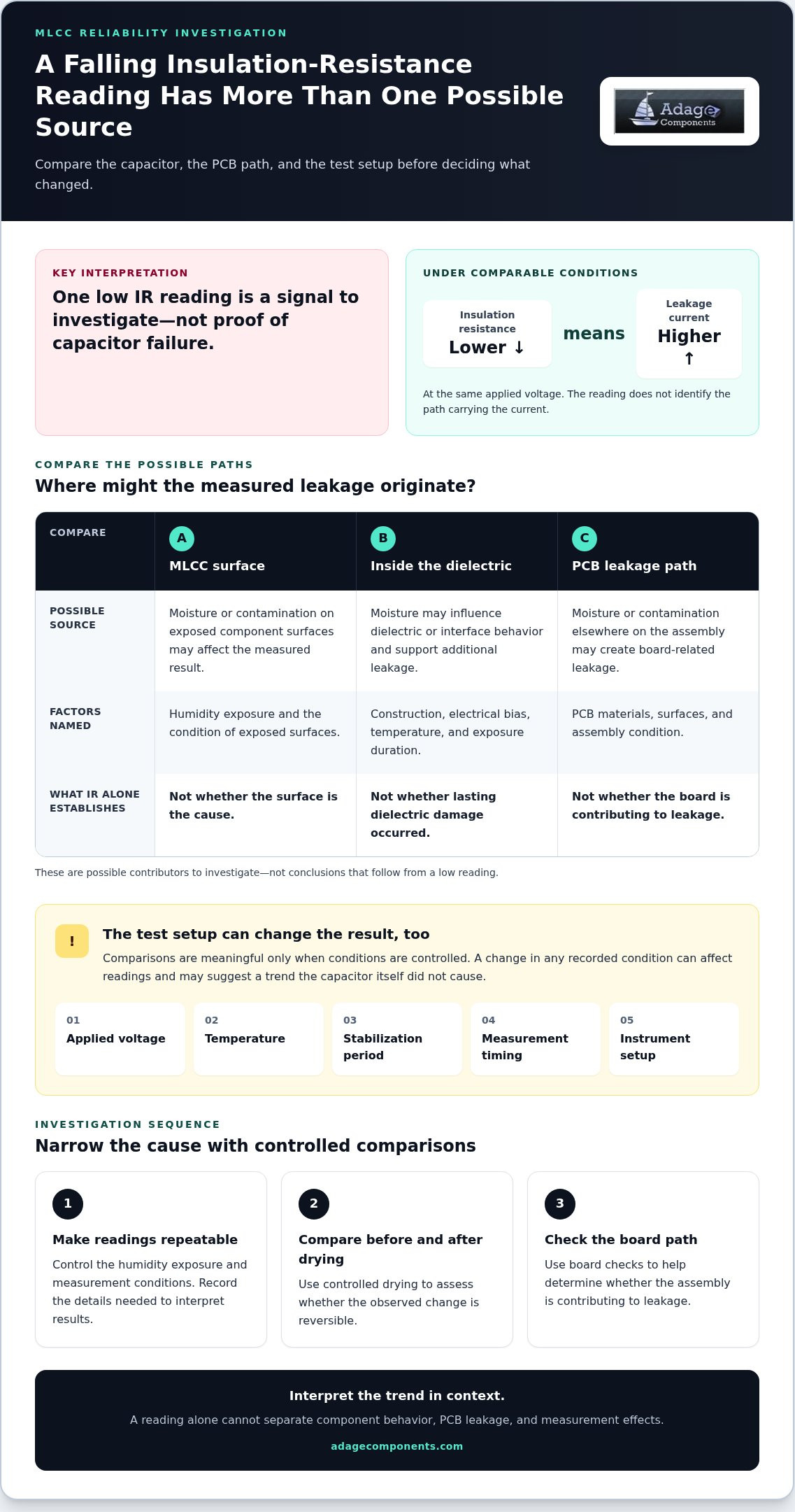
Insulation resistance (IR) describes how strongly a capacitor resists leakage current through its dielectric under specified test conditions. A lower IR reading means more current may flow at the same applied voltage, which can affect circuit behavior when leakage matters to the design. Treat the result as a measurement trend to investigate, not proof by itself that a capacitor has failed or why a reading changed.
Humidity is one factor in that assessment, alongside applied voltage, temperature, contamination, component construction, and the condition of the complete assembly. The phrase ceramic capacitor insulation resistance degradation under humidity describes a change observed under particular conditions, not a single diagnosis that applies to every MLCC.
How insulation resistance relates to leakage current
Under comparable conditions, IR and leakage current move in opposite directions: lower resistance corresponds to higher leakage at the same voltage. That relationship makes IR useful for tracking insulation behavior, but it doesn’t identify the physical path carrying the current. In a mounted assembly, the reading may reflect surface or board-related leakage rather than current through the capacitor dielectric alone.
IR is distinct from capacitance, dissipation factor, and dielectric-withstanding measurements. Capacitance measures charge storage, while dissipation factor characterizes energy loss under specified AC conditions. A dielectric-withstanding test evaluates response to a prescribed high-voltage stress. These measurements answer different questions and can’t automatically substitute for an IR measurement.
Comparisons are meaningful only when test conditions are controlled. Record the applied voltage, temperature, stabilization period, measurement timing, and instrument setup. A change in any of these can affect readings, so comparing results taken under different conditions may suggest a trend the capacitor itself didn’t cause.
Why humidity exposure raises a reliability question
Moisture exposure is an environmental stress that can reveal weaknesses in a component or assembly. Ceramic capacitors contain ceramic dielectric layers and electrodes, but construction and material systems vary. The Ceramic Capacitor Overview provides background on common constructions and types; it doesn’t establish how a particular part will perform under humidity.
Observed effects can depend on the capacitor’s construction, electrical bias, temperature, exposure duration, and surrounding PCB materials and surfaces. Moisture or contamination on an assembly may influence the measured result, while changes within a component may also warrant investigation. The reading alone can’t separate these possibilities.
There is no universal IR threshold that establishes humidity damage for every ceramic capacitor. Acceptance limits must come from the applicable component specification or qualification requirement, with test conditions defined. Treat a decrease as a reliability signal: verify that measurements are comparable, then use controlled evaluation to determine whether the change is repeatable and relevant to the application.
How Humidity Can Contribute to Ceramic Capacitor IR Degradation
Humidity-related IR change can arise through more than one path. Moisture may collect on exposed surfaces, affect a component’s dielectric system, or interact with residues and materials elsewhere in the assembly. These are mechanisms to investigate, not conclusions that follow from a low reading. The observed response depends on the capacitor’s construction, materials, manufacturing quality, board condition, and the conditions applied during exposure and measurement.
Moisture, dielectric behavior, and internal leakage paths
Within an MLCC, moisture exposure may influence dielectric or interface behavior and create conditions that support additional leakage. Grain boundaries and interfaces are possible areas of interest in ceramic materials, but an IR result can’t establish that either has changed. Ceramic dielectric classes and component constructions differ, so avoid assigning one mechanism to every capacitor or treating a dielectric label as a humidity-performance guarantee.
Construction and process control can affect susceptibility, but confirm any proposed material-specific explanation against primary research on the relevant part and test conditions. Physical defects also matter: the NASA report on ceramic capacitor IR examines insulation resistance, leakage current, cracks, and measurement. It offers useful context for interpreting leakage, but a crack-related finding doesn’t by itself explain a humidity-associated change in a particular sample.
Bias, temperature, and electrochemical effects
Applied voltage and temperature should be treated as interacting test variables. Bias can influence the electrical response of moisture-affected paths, while temperature can change measured behavior and the conditions under which those paths develop. Neither variable alone proves electrochemical degradation. Electrochemical migration or corrosion is a possibility to investigate only when supported by relevant physical evidence and research for the material system.
Keep the causal sequence clear. Compare measurements from samples with controlled exposure and consistent voltage, temperature, and timing. If the reading changes during exposure and then moves toward its baseline after controlled drying or stabilization, that recovery suggests a reversible contribution may be present. It doesn’t prove that no lasting change occurred. A persistent shift also warrants investigation, but doesn’t identify its location or mechanism by itself.
For a useful investigation, separate observations from interpretation:
- Before exposure: Record the sample identity, board condition, and baseline IR under defined measurement conditions.
- During exposure: Document humidity, temperature, duration, and whether electrical bias was applied.
- After exposure: Measure at a consistent time and temperature, then compare the result with baseline and any controlled recovery reading.
- When readings remain abnormal: Examine the component and assembly for evidence that can distinguish internal change from surface leakage or physical damage.
This sequence helps prevent a measurement trend from becoming an unsupported failure diagnosis. For component comparison, Adage Components’ MLCC product linecard can help identify relevant capacitor options. Assess humidity suitability against documented requirements and validation evidence.
Is the MLCC, the PCB, or the Test Setup Causing the IR Drop?
A low reading alone doesn’t establish capacitor failure. In an assembled product, leakage may pass through the MLCC, along a moisture-affected board surface, or through a measurement path that includes the fixture and connections. Compare results before humidity exposure, immediately after exposure, and after controlled recovery. Keep voltage, temperature, humidity, elapsed time, fixture, and sample history consistent so the comparison is meaningful.
Signs that point toward board contamination or surface leakage
Board-level leakage deserves attention if low IR remains at the unpopulated pads or varies with cleaning, handling, or drying history. Record the board’s condition and any cleaning process before comparing results. Residues can attract moisture, while close spacing can make a surface path more consequential. A pad measurement helps separate board contribution from the removed part, but it doesn’t identify the specific contaminant or prove the capacitor is sound.
Signs that point toward the component or measurement method
If isolated capacitors show a similar, repeatable shift while the board reading is stable, component-level investigation becomes more relevant. Check sample-to-sample consistency before drawing that conclusion. Also review instrument range, fixture leakage, guarding, contact quality, and stabilization time. Recovery after drying is useful evidence, but it can’t identify a single mechanism or rule out lasting change.
Use a controlled sequence to narrow the cause: compare baseline readings, repeat the same measurement after exposure, then measure again after a defined recovery condition. Log each sample’s identity and history, and avoid changing multiple variables at once. If the board remains low after component removal, focus the next checks on the board and measurement path. If only the isolated part remains low, preserve the sample and test records for further evaluation. This approach keeps ceramic capacitor insulation resistance degradation under humidity from becoming an unsupported failure label and gives engineering and procurement teams clearer evidence for corrective action.
How to Investigate and Mitigate Humidity-Related IR Degradation
A reliable investigation turns a low reading into a controlled comparison. Define the symptom first, then change one variable at a time. This helps distinguish an exposure effect from handling, board condition, or measurement variation, and gives engineering teams evidence they can use to select corrective action.
Set up a controlled humidity investigation
Before testing, define the failure symptom and establish baseline readings for the component or assembly. Document the applicable test method and revision after confirming they fit the device, application, and qualification objective. Keep control and exposed samples under consistent handling so the comparison reflects the planned stress rather than differences in preparation.
- Identify the samples. Record part identity, sample history, board condition, and whether each capacitor is tested individually or as part of an assembly.
- Set the baseline. Measure IR using a documented voltage, temperature, fixture, stabilization period, and measurement timing. Record instrument details and repeat readings as needed to assess consistency.
- Control exposure. Log humidity, temperature, duration, applied bias, and any transitions into or out of the environment. Keep control samples unexposed while maintaining comparable storage and handling.
- Measure and compare. Use the same setup and timing for post-exposure readings. If recovery is being assessed, define the recovery conditions and record when each measurement occurs.
- Inspect after testing. Review the component, board, and measurement connections. If the procedure permits, compare the populated assembly with the unpopulated board pads or an isolated capacitor.
Keep the full record together. Sample identity, board condition, voltage, temperature, humidity, exposure duration, and measurement timing are essential context for interpreting a trend. Without them, a difference between readings may be difficult to attribute or reproduce.
Reduce recurrence through design and process controls
Match the corrective action to the evidence. If board-surface leakage is implicated, review cleanliness, residue control, handling, pad spacing, and the assembly process. If the system faces sustained humidity or condensation risk, assess enclosure and environmental controls. If measurements vary with the fixture or contact method, correct the setup and repeat the evaluation before changing the design.
For a component-level concern, review the MLCC against actual operating conditions and documented qualification requirements. Avoid universal pass/fail thresholds; use the applicable component specification and system acceptance criteria. Evaluate any mitigation, including a process change, protective measure, or replacement part, on representative assemblies before applying it across a product family.
This disciplined workflow makes ceramic capacitor insulation resistance degradation under humidity easier to investigate without treating a single result as a diagnosis. For component evaluation, compare the relevant MLCC options against your application requirements and retain the supporting test records with the selection decision.
Selecting and Sourcing MLCCs After Humidity-Related IR Degradation
Use your investigation results to define what a replacement must do, not just what it must physically replace. A useful specification connects original design requirements with observed conditions and qualification evidence. That gives engineering and procurement teams a controlled basis for comparison, rather than relying on a dielectric label or footprint alone.
Build a technically useful MLCC replacement requirement
Start with the existing part number and capture the requirements that affect fit, function, and reliability. Include the application and conditions associated with the IR change. A pin-for-pin match is a starting point, not proof of electrical or environmental equivalence.
- Electrical: Record capacitance, tolerance, rated voltage, dielectric designation, and other circuit-critical requirements.
- Mechanical: Specify package size, termination configuration, and mounting or clearance constraints.
- Environmental: Document operating conditions, humidity exposure, electrical bias, and relevant environmental stresses.
- Qualification: Include test conditions, failure observations, and the acceptance criteria for the component and system.
Compare candidate documentation against every requirement. A dielectric designation alone doesn’t establish humidity performance, and a matching package doesn’t confirm application suitability. Test samples under a relevant, documented plan before approving a change.
Connect component qualification with a verified supply chain
Adage Components provides authentic components through direct verified procurement channels and conducts in-person manufacturing audits worldwide. These supply-chain controls support component sourcing, but they aren’t proof of a specific MLCC’s insulation-resistance performance under humidity. Assess each candidate against its applicable documentation and your qualification requirements.
Pin-for-pin replacement support can include specification sheets and/or samples. This gives engineering teams materials to compare against the original part requirements and a basis for further evaluation.
Share your part requirements and bill of materials through the BOM submission form to support a sourcing comparison. Clear requirements connect humidity-related findings with a technically grounded replacement assessment and a verifiable procurement path.
Turn Reliability Findings Into a Confident Component Decision
Convert your investigation into a decision record that supports engineering approval and future procurement. Capture the conditions behind the insulation-resistance change, the corrective action selected, and the evidence required to validate any component change. That record helps keep qualification decisions consistent as designs, production needs, or sourcing conditions evolve.
For ceramic capacitor insulation resistance degradation under humidity, a disciplined link between test evidence and component requirements is more useful than a quick substitution based on footprint or dielectric label alone. Adage Components brings 30+ Years Experience to electronic component sourcing, with a focus on helping customers align component choices to documented needs.
Review Adage Components’ MLCC and component line card and submit your BOM to support your next sourcing evaluation. With clear requirements and a considered qualification path, your team can move forward with greater confidence in its component decisions.
Frequently Asked Questions
Does high humidity always reduce ceramic capacitor insulation resistance?
No. Ceramic capacitor insulation resistance degradation under humidity is not an inevitable outcome of exposure; response varies with part construction and the assembled product. Two capacitors tested at the same chamber setting may produce different readings if their board condition, bias history, or measurement timing differs. Treat humidity as a condition to evaluate, then compare matched samples and controls before changing the part specification.
Can an MLCC’s insulation resistance recover after humidity exposure?
Yes, an IR reading may move closer to its pre-exposure level after controlled drying, but recovery alone can’t confirm whether moisture in the part, board-surface leakage, or another factor caused the shift. Keep post-exposure handling and measurement intervals consistent across samples. If only some units recover, retain those units and their records for separate inspection rather than averaging away the difference.
Should I measure an MLCC on the PCB or remove it first?
Measure in circuit when the question concerns assembled-system leakage, but don’t treat that value as the capacitor’s isolated IR. Neighboring components and board paths can affect the reading. An isolated-part measurement may help evaluate the component, provided removal doesn’t introduce damage or alter the test history. A useful comparison uses matched assemblies and loose samples, with the test method and sample handling documented.
Can conformal coating prevent humidity-related capacitor IR degradation?
Coating may be one element of an environmental protection strategy, but it can’t be assumed to prevent humidity-related IR changes. Results depend on coating coverage and process, board cleanliness before coating, and actual product exposure. Validate the proposed coating on representative assemblies, and retain untreated comparison units where practical. This helps determine whether the intervention addresses the observed path rather than masking it.
Does choosing X7R instead of another ceramic dielectric solve humidity-related IR loss?
No. X7R identifies a dielectric classification, not a universal humidity-endurance claim. MLCCs with the same designation can differ in construction, manufacturing process, package, and qualification evidence. Compare the candidate’s specifications and environmental qualification data with the application’s actual bias, temperature, and exposure conditions. If humidity drove the replacement decision, include that stress in validation instead of relying on dielectric designation alone.
Which information should an engineer collect before requesting an MLCC replacement?
Provide the existing part number and package, circuit function, required capacitance and voltage ratings, and footprint or termination constraints. Add environmental requirements and the conditions associated with the IR observation, including bias, temperature, humidity, duration, and measurement timing. Include acceptance criteria and recovery results as well. This context helps assess whether a candidate fits the application and has relevant documentation, not just matching nominal capacitance.
Disclaimer
Cross-referenced components needs to be confirmed by the client with either spec. sheet or samples or both.
Please note, we use AI to help us, information is verified to be correct but we can not guarantee 100% accuracy.


