

A 125C operating point doesn’t tell the full capacitance story. At 125C, capacitance drift in a high-temp ceramic capacitor can reflect both temperature-dependent change and dielectric ageing, and those effects follow different rules.
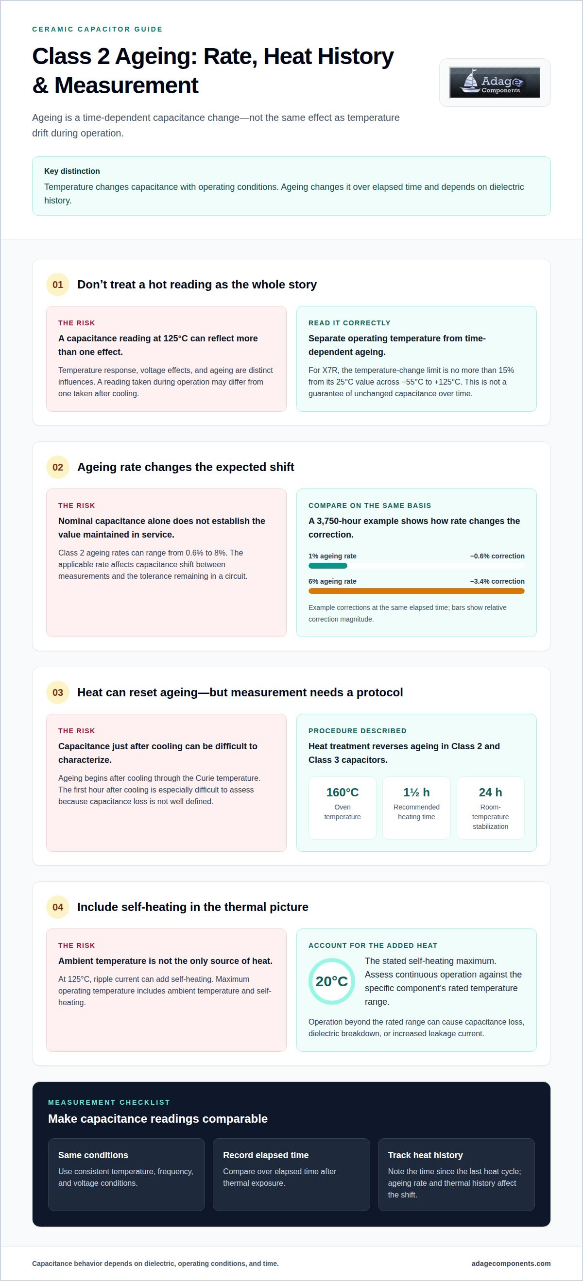
For an X7R capacitor, the capacitance change should stay within 15% of its 25C value across the specified range of -55 through +125C. That temperature limit isn’t the same as a guarantee that capacitance remains unchanged over time. Class 2 dielectrics also age, with capacitance loss commonly described against logarithmic time rather than as a fixed loss per hour.
This distinction matters when selecting a component for a circuit that must hold capacitance near its design value. The sections ahead explain how temperature changes capacitance, why Class 2 ageing continues after cooling, how to interpret ageing rates, and how the logarithmic loss law applies. They also clarify what a dielectric classification tells you, and where its limits end.
Key Takeaways
- Separate temperature-driven capacitance variation from voltage-bias effects; a dielectric class designation does not define both.
- Compare Class 2 ageing rates using the same time basis and thermal history to make the expected capacitance change meaningful.
- Use the logarithmic loss law to understand why ageing is expressed across time decades rather than as a constant hourly loss.
- Read ceramic capacitor standards as classification limits, not a complete prediction of an individual part’s behavior.
- For temperature-sensitive designs, match the dielectric and component requirements to the circuit’s operating conditions.
Temperature-dependent capacitance changes in ceramic capacitors
At 125°C, capacitance reflects both the dielectric’s temperature response and its operating history. High-temp ceramic capacitor capacitance drift at 125C is easier to assess when temperature effects are separated from voltage bias and ageing.
Capacitance Testing Conditions
Capacitance testing measures a component under defined temperature, frequency, and voltage conditions. These parameters matter because readings taken under different conditions may not be comparable, even for the same device.
For surface-mount X7R capacitors, the stated test frequency is 1 kHz. The test voltage is 0.5 V rms for ratings at or below 25 V, and 1.0 V rms above 25 V. Ceramic capacitors are normally characterized at no more than 1 volt because applied voltage can substantially affect their properties. Record the measurement conditions alongside capacitance values to distinguish an actual change from a test setup difference.
Temperature Characteristics Across Ceramic Types
Temperature-characteristic codes classify ceramics by how capacitance changes across a specified temperature range. They help identify whether a design prioritizes stable capacitance or higher capacitance in a compact component.
X5R, X6S, and X7R are Class II designations with distinct temperature characteristics. X7R should change no more than 15% from its 25°C value across -55 through +125°C. C0G, also called NP0, has a temperature drift of ±30 ppm/°C over -55 to 125°C. U2J is another temperature-characteristic code; use the individual part’s specified limits to understand its behavior in an application.
Temperature and Voltage Effects
Temperature and voltage can both affect measured capacitance, but they describe different effects. The temperature coefficient describes variation with temperature, while DC bias can shift capacitance independently.
X7R’s temperature designation does not specify its voltage coefficient. A 4.7 µF, 16 V X7R example measured 1.5 µF under a 12 V bias. This illustrates why nominal capacitance alone may not represent the effective value in a circuit. Assessing high-temp ceramic capacitor capacitance drift at 125C means considering operating temperature and applied voltage together, while keeping their effects distinct.
Drift and Aging at 125°C
There is no single capacitance drift value for every ceramic capacitor at 125°C. X7R’s temperature-change limit is no more than 15% from its 25°C value across -55 through +125°C; voltage effects and ageing are separate influences.
Ageing is a time-dependent change in capacitance, distinct from temperature-driven variation. Class 2 and 3 ceramics can undergo structural changes, and barium-titanate dielectrics have a Curie temperature of approximately 125°C. Elevated operating temperatures can cause potential de-ageing. To measure ageing, compare capacitance over elapsed time after thermal exposure, using consistent temperature, frequency, and voltage conditions. A reading taken during operation may differ from one taken after cooling.
Ageing rates for ceramic dielectric classes
Ageing is a time-dependent change in dielectric structure, not simply temperature drift during operation. Class 2 and 3 multilayer ceramic capacitors can lose capacitance as their crystal structure shifts toward a lower-dielectric-constant form.
Class 2 High-Dielectric-Constant Capacitors
Class 2 capacitors use high-dielectric-constant ceramics to provide substantial capacitance in compact components. That benefit comes with ageing and voltage-induced capacitance changes, so nominal capacitance alone cannot establish the value maintained during service.
Class 2 ageing rates can range from 0.6% to 8%. The applicable rate affects how much capacitance shifts between measurements, and therefore how much tolerance remains in the circuit. A 3,750-hour example shows a -0.6% tolerance correction at a 1% ageing rate, compared with -3.4% at a 6% rate.
Barium Titanate Dielectrics
Barium titanate is a common dielectric material in Class 2 and Class 3 ceramic capacitors. Its crystal structure changes around its Curie temperature, approximately 125°C, and ageing begins after cooling.
A high dielectric constant helps a ceramic capacitor achieve high capacitance, but it does not make capacitance fixed. Prolonged exposure to high temperatures can accelerate structural changes and reduce capacitance over time. The shift depends on the dielectric’s ageing rate and the time since the last heat cycle.
Heat treatment can reset this ageing by returning the crystal structure toward its original state. Heating Class 2 and Class 3 capacitors above the Curie point reverses ageing; one recommended procedure uses an oven at 160°C for 1½ hours. Afterward, allow 24 hours of room-temperature stabilization before measuring capacitance. The first hour after cooling through the Curie temperature is especially difficult to characterize because capacitance loss is not well defined.
At 125°C, ripple current can add self-heating to the capacitor’s thermal exposure. Maximum operating temperature includes ambient temperature and self-heating; the stated self-heating maximum is 20°C. Account for this added heat when assessing continuous operation, because operation beyond the rated temperature range can cause capacitance loss, dielectric breakdown, or increased leakage current.
There is no single derating value for every ceramic capacitor. Reliability depends on the specific part’s rated temperature range, applied voltage, ripple-related heating, and dielectric class. Keep the operating conditions within the component’s ratings, and assess capacitance after thermal exposure using consistent measurement conditions. For component planning, the ceramic capacitor line card provides a relevant reference.
Capacitance change-rate ranges for Class 2 capacitors
A capacitance change rate describes ageing over time, not the full operating change in a circuit. For Class 2 parts, the stated rate is one input alongside initial tolerance, temperature behavior, and applied voltage. Treating these effects separately helps identify which source of variation consumes the circuit’s capacitance margin.
Class 1 and Class 2 ceramics serve different design priorities. Class 1 C0G is suitable for many common analog electronics applications, where stable capacitance matters. Class 2 ceramics offer higher dielectric constants and support greater capacitance in compact components. That trade-off makes the class selection consequential: high capacitance does not by itself indicate how closely a part will retain its value.
Manufacturers define dielectric classes by characteristic limits, but a class code does not predict every component’s exact behavior. Parts in the same class can differ in capacitance change, tolerance, and response to applied voltage. If a circuit requires a narrow capacitance range, assess the specific component’s stated limits rather than treating its class label as a complete performance curve.
Class 2 and Class 3 ceramics can age as their crystal structure shifts toward a lower-K form. The ageing rate expresses this time-related loss; it is not the same as the temperature coefficient or an instantaneous change under voltage. These distinctions matter when evaluating a measured value: a reading can reflect more than one mechanism, and the test conditions must be interpreted alongside the part’s ageing history.
Class I stability offers a useful contrast. C0G ageing is negligible, while high-dielectric-constant Class 2 materials have measurable ageing. The difference can guide component selection when a circuit prioritizes predictable capacitance over compactness or high capacitance. Typical design decisions weigh the required capacitance against allowed drift, tolerance, and operating conditions, rather than choosing by dielectric class alone.
For rate comparisons, use the same basis for elapsed time and measurement conditions. A rate from one part cannot be applied automatically to another Class 2 formulation, even if both carry the same broad classification. Record the initial capacitance, thermal history, applied voltage, and measurement point when assessing change. This separates ageing from temperature- or voltage-related variation and makes the resulting comparison useful for circuit design.
Logarithmic capacitance-loss law
Class 2 ageing is expressed across logarithmic time intervals, not as a fixed hourly loss. This distinction changes how engineers interpret capacitance values measured at different ages. A device with a stated ageing rate loses capacitance progressively, while the percentage change per decade remains the useful comparison basis.
For example, a 1% ageing rate means capacitance decreases by 1% between 1 and 10 hours of age. A decade is a tenfold increase in elapsed time, so equal intervals on a logarithmic time scale provide the comparison. The rate does not mean that the capacitor loses 1% every hour. Extending the hourly figure linearly would misrepresent the ageing law.
Z5U ceramic capacitors have a typical ageing rate of 6% per logarithmic decade. That rate describes time-dependent loss, not the temperature coefficient or capacitance change caused by applied voltage. Keep those effects separate when comparing a measured value with nominal capacitance. The dielectric class, elapsed time, temperature, and measurement conditions each shape the reading.
DC bias introduces another change. A 4.7 µF, 6.3 V Y5V device in an 0603 package had a typical value of 0.33 µF under 5 V bias at room temperature. In one example, that value rose to 0.39 µF at +85°C under the same bias. This temperature-dependent response is not the logarithmic ageing law; it shows why a biased measurement needs its operating temperature recorded.
Temperature can also shift capacitance without applied bias. An example Y5V capacitor changed from 4.7 µF to 1.5 µF at +85°C, a 68.14% decrease. That snapshot describes temperature-related change, not capacitance loss accumulated over time. A temperature reference and a known age are both needed to distinguish these mechanisms in device measurements.
For a meaningful ageing comparison, measure capacitance at a consistent reference temperature and under consistent voltage and frequency conditions. Record the time since the last heating cycle, because thermal history affects the starting point for ageing measurements. Then compare readings at logarithmically spaced time intervals. This helps distinguish voltage-induced change, temperature response, and time-based loss in circuit analysis.
Bias comparisons can also reveal why package details matter when interpreting a measured capacitance. The example 4.7µF X7R capacitor in an 0805 package provided 1.53µF, or 32.6% of nominal capacitance, under a 12V bias. The example 4.7µF X7R capacitor in a 1206 package provided 3.43µF, or 73.0% of nominal capacitance, under a 12V bias. In the larger packages, the example 4.7µF X7R capacitor in a 1210 package provided 4.16µF, or 88.5% of nominal capacitance, under a 12V bias, while the example 4.7µF X7R capacitor in an 1812 package provided 4.18µF, or 88.9% of nominal capacitance, under a 12V bias.
These figures describe capacitance under applied voltage, not the loss accumulated as a component ages. Comparisons across packages are meaningful only when the bias condition is also considered, since nominal capacitance alone does not show the value available in operation. Record package and bias information alongside age, temperature, and measurement conditions. This helps separate a voltage-dependent reading from the progressive change described by the logarithmic capacitance-loss law. Repeated measurements under matched conditions can then reveal time-related change without mistaking an initial bias-related difference for ageing.
Ceramic capacitor standards
Ceramic capacitor standards define temperature characteristics as industry groupings, not complete predictions of individual parts. This distinction matters when a rating informs a design decision: components in the same classification can behave differently while remaining within its specified limits.
For example, X7R identifies a temperature characteristic, but does not define the part’s voltage coefficient. Its specified capacitance change is no more than 15% from the 25°C value across -55 through +125°C. That limit describes the classification’s temperature behavior, not every capacitance shift caused by voltage, ageing, or measurement conditions. Treat the code as a boundary, not a full operating curve.
The EIA temperature-compensation specifications for ceramic capacitors are identified as EIA-198. EIA temperature coefficients for temperature-compensating ceramics span 0 to -750 ppm/°C. This framework describes a characteristic range; the precise response of a capacitor still depends on its specific dielectric and construction. EIA-198 therefore provides a common classification reference, while the part’s rating supplies the relevant component-level limits.
Reference conditions also affect comparisons. For temperature-compensating ceramics, the EIA reference temperature is 25°C, while the JIS reference temperature is 20°C. CECC gives a capacitance reference temperature of 20°C ± 2°C. A capacitance value measured against one reference may not be directly comparable with a value measured against another. Include the reference temperature when interpreting specified tolerance or stability.
Ageing has its own reference point. The standard reference age for specifying ceramic-capacitor capacitance tolerance is 1,000 hours after cooling through the Curie temperature. That convention matters because Class 2 and Class 3 ceramics continue ageing after cooling, changing capacitance over time. A tolerance rating without its ageing reference can therefore obscure when the stated value applies.
Not every code provides the same information. The JIS temperature-characteristic code B3 has no provisions for capacitance change, so the code alone cannot establish a stable capacitance range. Ceramic capacitor standards may use different classifications, so their requirements should not be assumed to be interchangeable. Their presence does not make all classifications interchangeable; interpret each code within its own standard and reference conditions.
The practical takeaway is to read the classification, reference temperature, ageing basis, and applied-voltage behavior as separate specifications. For component selection across ceramic capacitor categories, review the ceramic capacitor line card alongside the applicable part data.
Adage Components: Multilayer Ceramic Capacitors (MLCC)
Adage Components supplies multilayer ceramic capacitors (MLCC) for procurement teams specifying components for temperature-sensitive circuits. When reviewing options, align the required capacitance with the dielectric class, applied voltage, and operating temperature. These parameters help frame sourcing decisions alongside the capacitance changes discussed above. Adage Components also provides technical support to OEMs and EMS providers assessing component requirements.
We support component sourcing with manufacturer pricing and authentic components from vetted manufacturers and partner suppliers. For an MLCC requirement, share the relevant part specifications and sourcing needs so the discussion can stay focused on your application. Contact Adage Components to discuss your component requirements.
Turn capacitor requirements into a sourcing plan
For teams managing high-temperature ceramic capacitor capacitance drift at 125°C, the next step is to translate circuit requirements into a clear component brief. Capture the required capacitance behavior under actual operating conditions, then align the specification with the design’s tolerance and sourcing needs. This gives procurement and engineering a shared basis for evaluating suitable parts.
Adage Components offers Multilayer Ceramic Capacitors (MLCC), alongside Thick Film Chip Resistors, Thin Film Precision Resistors, and Carbon Film Resistors. Include the relevant component requirements in your sourcing discussion to keep the review focused on your application and bill of materials.
Explore component offerings and take the next step toward a sourcing plan that supports your design requirements.
Frequently Asked Questions
How do Class I C0G and Class II X7R, X8R, and X7S capacitors compare at 125°C?
C0G offers a much tighter temperature characteristic: its drift is ±30 ppm/°C across -55°C to 125°C. X7R may change by up to 15% from its 25°C capacitance across that range, while X8R is designed for applications up to 150°C. X7S is also a Class II designation, but the specific part’s datasheet determines its temperature limits. Compare rated temperature, tolerance, and voltage response for the actual component.
What are the operating temperature ranges and capacitance tolerances of high-temperature ceramic capacitors?
Ranges and capacitance limits depend on the dielectric classification. X7R operates from -55°C through +125°C, with a permitted change of up to 15% from its 25°C value. X8R is designed for applications up to 150°C. C0G drift is ±30 ppm/°C from -55°C to 125°C. These temperature characteristics are separate from initial capacitance tolerance, so assess both when determining the usable capacitance in a design.
How do DC bias and applied voltage affect ceramic capacitor capacitance at 125°C?
DC bias can reduce the effective capacitance of Class II ceramics, and the X7R designation does not define a part’s voltage coefficient. For example, an 0805 1.0 µF X7R capacitor retained about 85% of nominal capacitance under bias. Treat that as an illustration, not a value for every device at 125°C. Evaluate the specific part at its operating voltage and temperature, using its capacitance-versus-bias data.
What do ceramic capacitor datasheets specify for temperature coefficient and capacitance change?
Datasheets identify the temperature characteristic or coefficient, capacitance tolerance, rated temperature range, and test conditions. For surface-mount X7R parts, capacitance testing is stated at 1 kHz. The test voltage is 0.5 V rms for ratings at or below 25 V, and 1.0 V rms above 25 V. Use these conditions to interpret the listed capacitance change, and distinguish temperature limits from voltage-dependent behavior.
How should capacitance be measured after stabilizing a ceramic capacitor at 125°C?
Measure the capacitor at a controlled 125°C after its temperature has stabilized, and record the test conditions with the result. For surface-mount X7R parts, use the stated 1 kHz test frequency and the appropriate test voltage: 0.5 V rms for ratings at or below 25 V, or 1.0 V rms above 25 V. Keep the measurement setup consistent, since changing temperature or voltage can change the reported capacitance.
Disclaimer
Cross-referenced components needs to be confirmed by the client with either spec. sheet or samples or both.
Please note, we use AI to help us, information is verified to be correct but we can not guarantee 100% accuracy.


