

Industrial MLCC qualification is not established by a single test. Applying MLCC qualification testing standards for industrial electronics means distinguishing component-level evidence from finished-equipment conformity: EMC testing evaluates emissions and immunity, while requirements depend on the product type and intended environment. A sound assessment connects the capacitor’s qualification records to the equipment and market where it will be used.
Engineering and procurement teams need more than a standards reference. They need evidence that can be interpreted consistently across suppliers, assessment bodies, and markets, along with technical records that support conformity decisions. International recognition can reduce duplicated assessment, but it does not eliminate the need to match evidence to the product’s requirements.
This article explains how ceramic capacitor standards relate to industrial qualification, how conformity assessment and mutual recognition affect cross-border acceptance, and which technical documents help keep decisions traceable. It clarifies where component test data ends and equipment-level compliance begins, helping qualification processes support informed sourcing and lifecycle decisions.
Key Takeaways
- Separate ceramic capacitor qualification tests from EMC assessment of the finished equipment to keep each compliance decision focused on the right requirements.
- For covered equipment, the EU EMC Directive 2014/30/EU requires it not to generate excessive electromagnetic disturbance or be susceptible to such disturbances in its intended environment, according to the European Union.
- Compare AEC-Q200 and IEC standards by their purpose and test scope before applying qualification evidence to an industrial use case.
- Use temperature, mechanical, and humidity test results to assess how an MLCC may perform under the stresses relevant to its application.
- Keep qualification records organized and traceable so technical evidence can support supplier reviews and conformity assessments across markets.
How do IEC 60384-21 and IEC 60384-22 specify testing for ceramic chip capacitors?
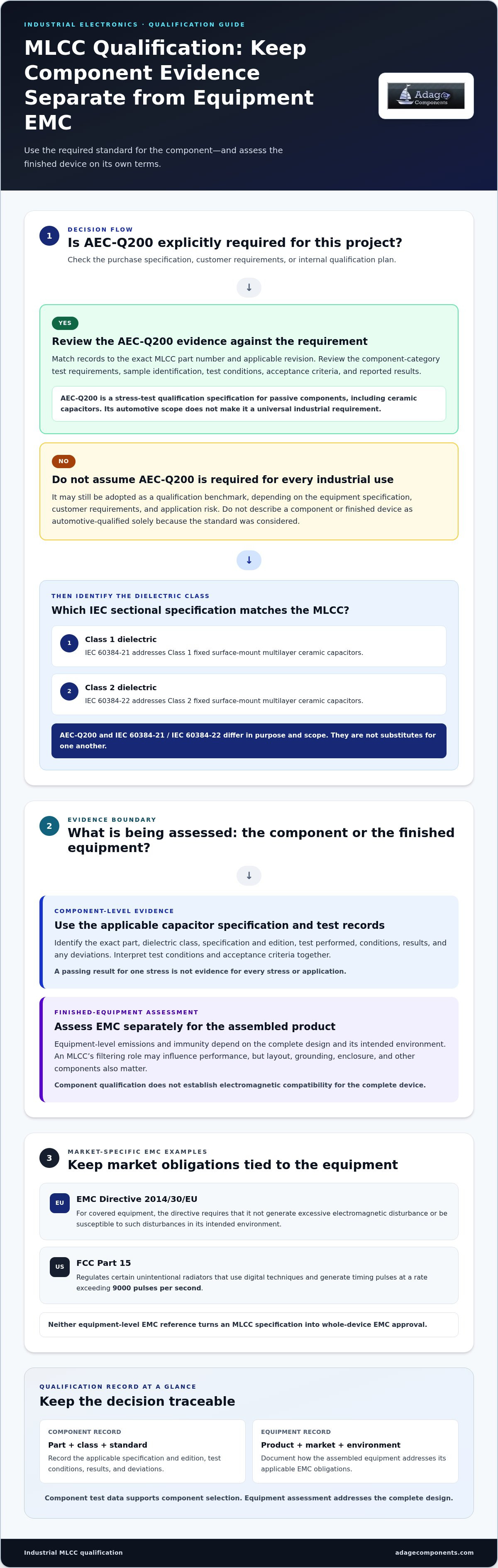
IEC 60384-21 and IEC 60384-22 are sectional specifications for fixed surface-mount multilayer ceramic capacitors. The first addresses Class 1 dielectric capacitors; the second addresses Class 2 dielectric capacitors. Their purpose is to define qualification and quality-assessment requirements for those component categories, rather than certify an entire industrial device. This distinction matters: an MLCC’s test record supports component selection, while finished-equipment compliance assesses the assembled product in its intended operating environment.
Each specification works within IEC 60384’s broader framework for fixed capacitors used in electronic equipment. In practice, qualification follows the applicable specification’s test sequence and acceptance criteria for the capacitor category. Engineers should match the part’s dielectric class and construction to the relevant specification, then compare its test evidence with the device design’s electrical and environmental demands. A Class 1 part and a Class 2 part are not interchangeable qualification cases merely because both use ceramic dielectric material.
Component evidence may include inspections and electrical or environmental test results defined by the applicable specification. The controlling edition and manufacturer data matter because test conditions and acceptance criteria must be interpreted together. A useful record identifies the exact part, dielectric class, specification and edition, test performed, conditions, results, and any deviations. For example, a capacitance-temperature result is meaningful only when its class and test conditions are clear. Do not treat one passing result as evidence for every stress or application.
System-level EMC requirements sit beside, not inside, this component qualification. According to the European Union, the EU EMC Directive 2014/30/EU requires covered equipment not to generate excessive electromagnetic disturbance or be susceptible to such disturbances in its intended environment. In the United States, according to the Federal Communications Commission, FCC Part 15 regulates certain unintentional radiators that use digital techniques and generate timing pulses at a rate exceeding 9000 pulses per second. Neither requirement turns an MLCC specification into whole-device EMC approval.
For industrial qualification, keep the two evidence tracks linked. Record the MLCC’s IEC 60384-21 or IEC 60384-22 basis, then document how the assembled equipment addresses its market-specific EMC obligations. A capacitor’s filtering role may influence emissions or immunity, but circuit layout, grounding, enclosure, and other components also affect system performance. This separation supports clear reviews: IEC component records establish what was assessed at part level, while device-level assessment addresses the complete design and intended environment.
Does AEC-Q200 apply to industrial MLCC qualification, and how does it differ from IEC standards?
AEC-Q200 can inform industrial MLCC qualification, but its automotive scope does not make it a universal industrial requirement. It is a stress-test qualification specification for passive components, including ceramic capacitors. Its relevance depends on the equipment specification, customer requirements, and application risk. An industrial design may adopt AEC-Q200 as a qualification benchmark without claiming that the component or finished equipment is automotive-qualified.
The distinction from IEC 60384-21 and IEC 60384-22 is purpose and scope. Those IEC specifications address fixed surface-mount multilayer ceramic capacitors by dielectric class. AEC-Q200 instead organizes stress tests for passive components under an automotive qualification framework. The standards are not substitutes: an IEC-qualified MLCC does not automatically satisfy an AEC-Q200 requirement, and AEC-Q200 evidence does not replace the relevant IEC specification.
For an industrial project, treat AEC-Q200 as applicable when a purchase specification, customer requirement, or internal qualification plan explicitly invokes it. Then match the component evidence to the exact MLCC part number and the applicable AEC-Q200 revision. Review the tests required for the component category, the sample identification, test conditions, acceptance criteria, and reported results. A test summary without traceable part and revision details is difficult to assess against a procurement requirement.
Qualification evidence also has boundaries. Passing component stress tests supports confidence in the tested part under the stated conditions; it does not establish suitability for every industrial environment. Board layout, mounting strain, operating voltage, ambient temperature, and exposure to moisture can affect application performance. Nor does AEC-Q200 demonstrate electromagnetic compatibility for the complete device. Equipment-level emissions and immunity remain separate design and assessment questions.
A practical comparison can keep the decision clear:
- IEC 60384-21 or IEC 60384-22: use the specification aligned with the MLCC’s dielectric class and component qualification needs.
- AEC-Q200: apply when the industrial requirement calls for its passive-component stress qualification or adopts it as a benchmark.
- Both: retain separate evidence for each requirement, and map every report to the component identity and test scope.
When reviewing sourcing options, compare the required qualification evidence with the capacitor specifications in the electronic component line card. That keeps the procurement record aligned with the engineering requirement, without treating an automotive qualification label as a substitute for application-specific review.
EMC testing evaluates device emissions and immunity to emissions from external sources, so it addresses a separate device-level question from MLCC qualification. IEC 61000-4-39 covers radiated-field immunity testing in close proximity and does not replace the general radiated immunity requirements in IEC 61000-4-3. In the United States, FCC Rules and Regulations Title 47, Part 15 specifies limits on radiation from intentional and unintentional radiation sources. FCC Part 15 regulates electromagnetic emissions but does not currently contain FCC regulations on product immunity to electromagnetic fields.
The page states that some categories of equipment, including industrial equipment, are specifically exempt from meeting FCC Part 15 requirements. For applicable emissions testing, the Federal Communications Commission gives the FCC Class A conducted quasi-peak emission limit from 0.15 to 0.50 MHz as 79 dBμV. These EMC requirements and test results should be reviewed separately from evidence that an MLCC meets a component qualification specification.
What are the MLCC temperature cycling, thermal shock, and operating temperature test requirements?
MLCC temperature qualification evaluates whether a ceramic capacitor remains functional across the temperatures and transitions specified for its application. Temperature cycling and thermal shock expose parts to changing temperatures, but use different transition profiles. Cycling uses controlled temperature stages, while thermal shock emphasizes rapid transitions between hot and cold conditions. The applicable specification and qualification plan set the actual limits, dwell periods, transfer method, and cycle count. One profile is not a substitute for the other.
A useful temperature-cycling record identifies the exact MLCC, test profile, and electrical measurements. Record baseline capacitance and insulation resistance, expose identified samples to the specified hot and cold stages, then repeat the measurements. The report should include dwell and transition conditions, sample count, observed failures, and acceptance criteria. These details let engineers compare results with the component requirement rather than rely on a generic “passed” statement.
Thermal shock assessment focuses on stress caused by rapid temperature changes. Fast expansion and contraction can challenge the ceramic body, internal electrode interfaces, and terminations. Inspect samples for physical damage, then compare electrical measurements against the defined pre-test and post-test criteria. A cracked body or changed electrical performance can affect reliability even when a part initially appears intact. Set the test profile from the governing qualification specification or project plan, not an assumed industry-wide temperature range.
Operating temperature is a separate selection and verification question. The MLCC’s rated range must cover the temperatures expected at its installed location, including heat from nearby power components and variation across operating modes. Board temperature can differ from ambient temperature, so assess the actual mounting environment. The component’s temperature characteristic also matters: Class 1 and Class 2 ceramic dielectrics behave differently as temperature changes. Check capacitance requirements across the intended range, not only at room conditions.
For industrial qualification, link each test to a defined design risk. A control cabinet with frequent startup and shutdown may make cycling evidence especially relevant; equipment near a hot process may require close review of maximum operating temperature. Document the selected profile, part identity, measurements, and acceptance decision together. This makes the basis for component selection traceable during design review, supplier changes, and later failure analysis.
- Temperature cycling: assess performance across controlled hot and cold stages.
- Thermal shock: evaluate response to rapid temperature transitions.
- Operating range: compare the MLCC rating with temperatures at its actual board location.
What MLCC mechanical tests are required, including vibration, shock, board flex, and terminal strength
There is no universal mechanical-test set for every MLCC. The applicable component specification, customer requirements, and equipment environment determine the qualification plan. Vibration and shock assess dynamic loading; board flex evaluates strain transferred through the printed circuit board. Terminal-strength testing checks the mechanical integrity of the capacitor’s terminations. These tests address different failure mechanisms, so passing one does not replace evidence for the others.
For vibration testing, the MLCC is typically mounted in a representative fixture or assembly and exposed to the specified vibration profile. The test plan defines the mounting method, orientation, frequency range, and exposure conditions. Inspect the part and measure relevant electrical characteristics before and after exposure. A capacitor near a vibrating motor, for example, may face a different board-level stress path from one on a rigid control-board assembly.
Mechanical shock applies a short, abrupt force to the mounted component. The governing qualification specification or project plan must define the profile and acceptance criteria. Review the board support and fixture design, since they affect how force reaches the MLCC. After exposure, inspect the body and terminations for visible damage, then compare electrical results with the defined limits. A cracked ceramic body can be difficult to detect without a deliberate inspection step.
Board flex testing focuses on bending strain during board handling, installation, or enclosure assembly. It assesses the mounted capacitor, not just the loose component. Board thickness, support points, component location, and orientation affect local strain. An MLCC near a board edge or fastener may experience more bending than one in a supported area. Record the board configuration and test method so results represent the intended assembly.
Terminal-strength evaluation checks whether the end terminations remain attached and functional under the mechanical loading specified for the part. Select a method that matches the component construction and applicable test plan. Record loading direction, fixture arrangement, inspection findings, and electrical measurements. Distinguish termination damage from ceramic cracking in failure reports, since corrective actions may differ.
A traceable qualification record links each result to the exact part number, mounting configuration, stress profile, and acceptance criteria. This prevents a vibration report for one board setup from being treated as proof for another. For industrial electronics, combine component-level mechanical evidence with assembly-level assessment when board strain or operating vibration creates risk. This provides a clearer basis for approving an MLCC in its actual mounting context.
How should MLCCs be qualified for humidity, moisture resistance, and biased temperature conditions
Humidity qualification checks whether moisture exposure changes an MLCC’s electrical performance or physical condition. The test profile must match the governing specification and intended operating environment. Industrial equipment may encounter humid air, condensation risk, or moisture exposure during storage and operation. These conditions are not interchangeable, so define the exposure before choosing the test method. Record the part number, dielectric class, sample condition, and applicable acceptance criteria.
For a controlled humidity assessment, take baseline measurements before exposure. Commonly reviewed characteristics include insulation resistance, capacitance, dissipation factor, and visible condition. Expose samples under the specified temperature, humidity, duration, and mounting arrangement, then measure them again under the procedure’s recovery conditions. Comparing results before and after exposure helps identify changes associated with moisture stress rather than normal measurement variation.
Biased humidity testing adds electrical stress during moisture exposure. The applied voltage and connection method should follow the MLCC qualification plan. Bias can reveal performance changes that unpowered humidity exposure may not show. Document voltage, polarity where relevant, fixture connections, exposure profile, and any interruptions. Do not infer a universal bias level or duration from the component category alone; these conditions must come from the applicable requirement.
Biased temperature-humidity assessment combines temperature and humidity with electrical stress. Elevated temperature can accelerate moisture-related mechanisms, while electrical bias tests the component under operating-like stress. Keep the chamber profile and electrical setup traceable to the exact sample group. After exposure, inspect for visible damage and compare electrical measurements with pre-test data and acceptance limits. Report individual failures and deviations, not just an overall pass statement.
Moisture-resistance records are useful only when the complete test context is preserved. Include the MLCC identity, lot information, mounting or fixture details, chamber conditions, bias, measurement method, and post-exposure results. This helps engineering teams compare evidence across suppliers and qualification runs. For example, a report for an unmounted component may not represent a board-mounted part exposed to assembly strain and operating voltage.
- Before exposure: identify samples and record baseline electrical measurements.
- During exposure: capture chamber conditions, mounting, and any applied bias.
- After exposure: document recovery conditions, inspection findings, and electrical changes.
For designs that also require resistance components, review the electronic component line card as part of broader BOM planning. Keep the resistor selection distinct from MLCC humidity qualification evidence, since each component requires its own applicable assessment.
Adage Components: Thick Film Chip Resistors
Adage Components offers thick film chip resistors and other resistor options for your BOM. We provide authentic components through vetted manufacturers and partner suppliers, many of them franchised by top 100 distributors. Our sourcing supports commercial and automotive grade components and compliance with all ISO certifications.
We combine an international logistics program with a growing state-of-the-art warehouse to support short lead times and supply planning that works with your MRP system. Our goal is to help products reach your facility in real time, on time. With manufacturer pricing and OEM pricing, you get the same advantages as buying from tier 1 distributors but at OEM pricing.
Contact Adage Components to discuss component requirements for your sourcing plan.
Turn qualification evidence into a controlled sourcing decision
Use MLCC qualification testing standards for industrial electronics to connect component approval with clear procurement requirements. Keep approved parts and revisions aligned between engineering and purchasing, so substitutions receive the same disciplined review as initial selections.
For your next BOM review, compare component options with Adage Components’ sourcing approach, including authentic components, manufacturer pricing, OEM pricing, and international logistics. This gives your team a practical route to evaluate cost and supply continuity alongside qualification needs.
Frequently Asked Questions
Which standards cover MLCC qualification testing for industrial electronics, including IEC, AEC-Q200, and MIL-PRF?
IEC 60384-21 and IEC 60384-22 address surface-mount ceramic capacitors by dielectric class. AEC-Q200 is relevant when a customer or project specification calls for automotive-style passive-component qualification. MIL-PRF specifications may apply to military procurement when the contract identifies a specific requirement. Treat these as distinct frameworks, not interchangeable certifications. For a cross-market design, map each required standard to the exact component, contract, and intended application.
What tests and acceptance criteria are required to qualify MLCCs for industrial applications?
The required test set follows the governing component specification and the project’s operating conditions. A qualification plan may include electrical measurements, temperature exposure, mechanical stress, or moisture testing. Acceptance criteria should define measurable limits for each characteristic, such as allowable capacitance change or insulation resistance. For a control cabinet near a motor, for example, address the actual environmental and mounting stresses rather than relying on a generic pass label.
What electrical reliability tests are required for MLCCs, including capacitance, insulation resistance, voltage, and life testing?
Electrical qualification commonly evaluates capacitance, insulation resistance, voltage withstand, and performance after life exposure. Capacitance testing checks whether the part remains within its specified range; insulation resistance assesses leakage behavior. Voltage testing evaluates the component under the conditions defined by its specification, while life testing tracks electrical change during sustained stress. Record test conditions and before-and-after results, then compare each measurement with the part’s acceptance criteria and circuit requirements.
What are the risks of using commercial-grade MLCCs in industrial electronics, and what derating or screening is recommended?
Passing component stress tests does not establish suitability for every industrial environment. Board layout, mounting strain, operating voltage, ambient temperature, and moisture can all affect performance.
Disclaimer
Cross-referenced components needs to be confirmed by the client with either spec. sheet or samples or both.
Please note, we use AI to help us, information is verified to be correct but we can not guarantee 100% accuracy.


