

An MLCC can turn electrical switching into audible sound and unwanted signal disturbance. Effective MLCC acoustic microphonics elimination techniques address the cause: Class II ceramic deforms under an electric field, and the PCB can amplify that movement into sound. Mechanical vibration can also induce voltage across the capacitor, affecting sensitive analog and audio circuits.
A faint buzz may seem like a mechanical nuisance, but it can point to a design interaction between the capacitor, its drive conditions, and the board. The vibration can fall within the human hearing range of 20 Hz to 20 kHz, while microphonics can matter even when no sound is obvious.
This article explains why Class II MLCCs sing, how electrical conditions and board mechanics shape the problem, and which design choices can reduce it. It covers how terminal construction, component placement, board rigidity, and vibration isolation affect acoustic output, and why precision analog and audio circuits need a separate check for electrically coupled microphonics.
Key Takeaways
- Class II MLCCs can convert electrical drive into mechanical movement, while the PCB can amplify that movement into audible noise.
- Metal terminals and leaded constructions can reduce vibration transfer to the board, but terminal design may affect electrical impedance.
- Board rigidity and component position influence acoustic output; mounting points and stiffeners can help limit vibration.
- In precision analog and audio circuits, capacitor movement can create an unwanted voltage signal even when audible noise is absent.
- Compare voltage-fluctuation and sound-frequency behavior, and validate candidate changes on the actual board assembly.
What Causes Capacitor Acoustic Noise (Singing Capacitors)?
Class II MLCCs can convert changes in electrical voltage into mechanical vibration, then transfer that movement through solder joints into the PCB. The board can amplify and radiate the vibration as audible acoustic noise.
For noise-sensitive designs, first identify whether the source is electrical excitation, mechanical coupling, or both. That distinction guides component selection, circuit changes, mounting choices, and simulation.
Piezoelectric Vibration and Noise Generation
Piezoelectric vibration occurs when an electric field deforms the ferroelectric ceramic inside a Class II MLCC. Repeated expansion and contraction can move the component by a few nanometers to micrometers, enough to excite a PCB resonance and produce audible sound. The board acts as a mechanical radiator, so the capacitor’s sound level depends on both its construction and the surrounding assembly.
Class I C0G/NP0 MLCCs are described as not exhibiting the piezoelectric effect, making them an option where their capacitance fits the design. Their lower capacitance density can make them impractical for requirements above 0.1 μF.
Electrical Conditions That Trigger Noise
Electrical conditions trigger noise when voltage changes across the MLCC repeatedly drive its ceramic body. The converter’s switching frequency need not fall within the audible range: burst packets, subharmonics, beat frequencies, or control-loop behavior can create lower-frequency excitation. A reported LED-driver example became inaudible to its builder after the oscillator frequency rose from 10 kHz to approximately 20 kHz, though that circuit-specific result is not a universal design rule.
Reducing voltage variation across the capacitor can reduce vibration. Review DC bias, load-transient response, line-transient response, and dielectric selection. A smaller-case MLCC or one with a lower dielectric constant may also reduce its acoustic contribution.
Low-acoustic-noise designs can use mechanically decoupled constructions. Leaded MLCC structures absorb some expansion and contraction before it reaches the PCB, while metal-terminal constructions can reduce vibration transmitted to the board. Metal terminals can also increase ESR and impedance, particularly at higher frequencies, so assess electrical performance alongside acoustic behavior.
For noise-sensitive designs, tantalum, polymer, or film capacitors avoid the ferroelectric MLCC mechanism. Their tradeoffs include differences in capacitance, size, and electrical performance. The right choice depends on the circuit’s capacitance, frequency, and transient requirements.
To reduce microphonics through selection and derating, compare dielectric type, case size, capacitance, and DC-bias behavior at the actual operating voltage. Reducing applied DC bias or choosing an MLCC with less DC-bias effect can limit noise, while C0G/NP0 may suit designs that can accept its lower capacitance density.
Series resistance or a damping network can reduce resonant excitation, while circuit changes can reduce voltage swing or transient variation across the MLCC. These changes may also affect power dissipation, response, or stability, so assess them in the complete circuit rather than treating sound alone as the design target.
Mitigation can add components, board area, and design-validation work; resistance can also dissipate power. Ordinary acoustic vibration does not generally indicate a reliability failure, but potting or thick conformal coating may damp sound without removing its cause.
Simulation can help compare electrical waveforms with PCB mechanical behavior and identify likely excitation paths. Treat the model as a design aid, then evaluate candidate constructions on the actual assembly, because mounting, board resonance, and component placement shape the final acoustic result.
Metal-terminal MLCCs and vibration isolation
Terminal construction, solder geometry, and PCB layout determine how much MLCC movement reaches the board. These mechanical paths matter because the PCB can turn local component vibration into radiated sound.
Solder Fillets and Vibration Transfer
A solder fillet forms part of the mechanical connection between an MLCC termination and the PCB. Its height and shape can change how strongly component movement couples into the board, so assembly geometry affects acoustic output.
A horizontally mounted MLCC with a small solder fillet is associated with the lowest acoustic noise. If the fillet rises above the halfway point of the termination, a vertically mounted MLCC can produce less noise than a horizontal one. These configurations show why orientation and solder profile should be assessed together.
PCB Layout and Vibration Cancellation
PCB layout can reduce vibration by positioning capacitors so their mechanical movement counteracts rather than reinforces board flex. On a double-sided board, capacitors placed on opposite sides can help cancel flexing. Matching identical MLCCs at the same X/Y coordinates on opposite layers also supports this approach.
Placement changes should preserve electrical routing and assembly requirements. A capacitor near the board edge may behave differently from one near a supported region, so compare candidate locations on the complete layout. In flexible PCB areas, a U-shaped slot around an MLCC can limit vibration propagation through the surrounding material.
PCB Vibration and Acoustic Resonance
Acoustic resonance occurs when periodic MLCC movement excites a board vibration mode. The board then radiates sound, and a change in PCB rigidity or mass can shift the sound frequency rather than simply reduce its amplitude.
Thickness is one design variable: example PCB thicknesses include 1.2 mm, 1.6 mm, and 2.0 mm. A thicker substrate increases rigidity, which can reduce acoustic amplitude; a thickness of 1.6 mm or more is one cited FR4 example. Validate these changes against electrical and mechanical constraints.
Effects of Component and Board Vibration
MLCC vibration can become audible when the board radiates the movement. It can also affect nearby components through shared mechanical coupling, particularly when several capacitors excite the same PCB region. Consider the converter’s applied electrical waveform and the board’s mechanical response together.
Metal-terminal and leaded constructions interrupt some vibration transfer between the capacitor body and PCB. Their effect depends on the assembly, including termination, orientation, and solder profile. Compare replacement candidates on the actual board, since component-only evaluation cannot capture board resonance or mounting behavior.
Use a staged evaluation: compare terminal construction, solder profile, and board placement while keeping the electrical function consistent. This helps isolate which mechanical path changes the acoustic response, rather than combining several layout changes at once.
For component comparisons alongside these layout decisions, the capacitor and component linecard provides a relevant selection reference.
Piezoelectric and electrostrictive behavior in Class II MLCCs
Class II ceramic capacitors can change shape under applied voltage through piezoelectric and electrostrictive effects. This distinction helps explain why voltage conditions and ceramic composition influence MLCC acoustic noise.
Piezoelectric Behavior in Class II MLCCs
Piezoelectric behavior is the coupling between electrical polarization and mechanical strain in a material. In a Class II MLCC, the applied electric field can deform the ferroelectric ceramic; vibration then passes through the component’s mounting into the substrate. The PCB can radiate that movement as sound, while mechanical stress can also produce a voltage signal.
Barium titanate, used in many Class II dielectrics, becomes tetragonal below its Curie temperature of 125°C. This crystal structure supports ferroelectric polarization, which helps explain the material’s electrical-mechanical response. C0G/NP0 Class I ceramics differ: they are described as not exhibiting the piezoelectric effect.
Under alternating voltage, repeated strain in the ceramic can produce periodic motion. Its amplitude and frequency depend on the applied waveform, material response, and mechanical mounting. The PCB’s own vibration modes determine whether that movement stays localized or becomes audible.
Electrostrictive Behavior in Class II MLCCs
Electrostriction is a voltage-driven change in material dimensions linked to the square of the electric field. Unlike the usual linear description of piezoelectric response, electrostrictive strain depends on field magnitude and can occur broadly in dielectric materials. In ferroelectric Class II ceramics, both behaviors can contribute to deformation.
This distinction matters because changing voltage can create changing strain even when designers do not identify a simple piezoelectric resonance. DC bias establishes the operating point, while ripple or transient voltage changes alter the field. The resulting mechanical response depends on ceramic composition and the voltage waveform.
For design analysis, separate electrical excitation from mechanical response. Examine the voltage across the MLCC during steady operation and load or line transients, then consider how the substrate responds. A simulation that models only electrical behavior may miss board vibration; mechanical analysis adds the structural path from ceramic strain to radiated sound.
These effects explain why two capacitors with similar nominal capacitance can behave differently acoustically. Dielectric formulation, case geometry, applied voltage, and mounting all influence the coupled response. Compare candidates under the intended operating conditions rather than relying on capacitance value alone.
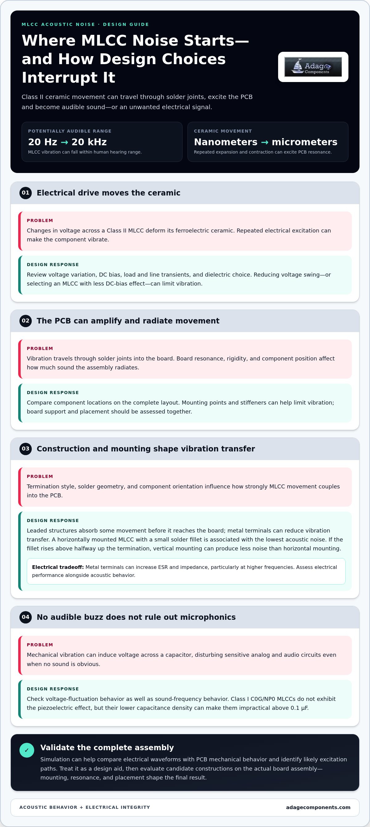
Placement near mounting points and stiffeners
PCB support affects how ceramic-capacitor vibration travels through an assembly. Placement near mounting holes or stiffeners can limit board motion, while unsupported regions and edges may radiate more sound.
Start by mapping noisy MLCCs against mounting points, stiffeners, and unsupported spans. Move a candidate capacitor closer to a supported region, then compare acoustic output under the same converter load and ripple conditions. This isolates the placement effect from changes in voltage or operating frequency.
Keep the MLCC’s longest dimension parallel to the PCB’s shorter side. This orientation reduces the mechanical lever effect that can drive board flex. On a double-sided layout, matching identical capacitors at the same X/Y coordinates can also help reduce vibration. Check that these positions suit the electrical routing and surrounding components.
Horizontal mounting is a useful configuration to evaluate, particularly with a small solder fillet. If the solder fillet rises above the termination’s halfway point, vertical mounting may produce less acoustic noise than horizontal mounting. The outcome depends on the actual assembly, so compare orientations using the intended solder profile.
Board rigidity is another layout variable. A thicker FR4 substrate, such as 1.6 mm or more, can increase rigidity and reduce acoustic amplitude. PCB thickness also changes board mass, which can shift the sound frequency rather than eliminate vibration. Evaluate rigidity alongside enclosure support and mounting constraints.
A practical layout review distinguishes supported and unsupported regions before component positions change. Mounting holes and stiffeners provide useful reference points; edges and flexible spans deserve closer attention. If a noisy capacitor sits near an unsupported edge, relocating it toward a support can change how its vibration couples into the board.
Assess reliability as well as sound. A revised placement must preserve the required electrical connections, assembly access, and mechanical support. Compare candidate layouts on the complete board, since PCB shape, mounting, and nearby components affect acoustic behavior. Keep applied voltage and converter conditions consistent during each comparison.
Use a controlled evaluation: document the original capacitor position, change one placement or orientation variable, and measure the resulting acoustic response. If moving an MLCC changes the sound frequency, the board’s mechanical response has shifted. Validate the final layout on the actual assembly before adopting the change.
Microphonics in precision analog and audio circuits
In a precision circuit, an MLCC can act as both a capacitor and a vibration-sensitive transducer. Mechanical movement may create voltage across its terminals, adding an unwanted signal even when the component produces no audible sound. This distinction matters in audio paths and other circuits where small voltage changes can affect the intended output.
Diagnose the electrical symptom separately from acoustic noise. Compare the frequency spectrum of the capacitor’s voltage fluctuation with the sound-pressure-level frequency characteristics. Matching peaks suggest a shared excitation path; a voltage signal without a corresponding audible peak can still indicate microphonics. This comparison helps distinguish electrical interference from a purely mechanical noise complaint.
A practical bench test uses a controlled tap on the PCB while monitoring circuit output with an oscilloscope. A repeatable output transient after the tap points to mechanical sensitivity in the assembly. Observe the signal at the affected circuit node, then compare the response with the board undisturbed. This test identifies susceptibility, but not the specific capacitor on its own.
To isolate the component, change one variable at a time. Compare the output with the suspect MLCC in circuit and with a mechanically different candidate that meets the electrical requirement. Keep the applied signal and measurement point consistent. If the output response changes, examine dielectric material, mounting, and position as possible contributors.
Dielectric choice matters because ceramic materials respond differently to electrical and mechanical excitation. A capacitor that meets nominal capacitance can still couple vibration into a sensitive node. Review the actual circuit function: a decoupling position, feedback network, and high-impedance input can react differently to the same induced voltage. Focus tests on nodes where a small disturbance can alter gain, offset, or recorded audio.
Terminals and board mechanics also shape the signal path. If tapping the PCB produces a repeatable waveform, compare the response after changing the capacitor’s location or mechanical connection. Then check whether output amplitude changes under the same test stimulus. This keeps diagnosis focused on measured circuit behavior rather than perceived loudness alone.
For audio designs, inspect both the electrical output and any audible artifact. A quiet component can still create a measurable signal, while a noticeable buzz may not enter the audio path. Use spectrum comparison and oscilloscope monitoring together to establish whether the MLCC affects the circuit, the board’s sound, or both. These are practical MLCC acoustic microphonics elimination techniques for locating the relevant coupling path.
Apply MLCC acoustic microphonics elimination techniques by matching the test to the circuit’s actual failure mode, then compare validated component options. The component linecard can help with component selection for precision circuit designs.
Adage Components: Thick Film Chip Resistors
Adage Components supports OEM and EMS procurement with Thick Film Chip Resistors, Thin Film Precision Resistors, and Carbon Film Resistors. For designs that include resistor changes alongside capacitor decisions, the team can help align component sourcing with your bill of materials.
We source authentic components through direct, verified procurement channels and use manufacturing audits to support quality assurance. OEMs can access manufacturer and OEM pricing, while international logistics support supply planning and shorter-than-average lead times. These capabilities connect component requirements with a cost-conscious procurement strategy.
Contact Adage Components to discuss your component requirements.
Make the Next Design Review More Decisive
Carry the acoustic issue into your next design review as a defined engineering requirement. Record the affected operating conditions, the circuit nodes that need protection, and the measurement method for assessing the revised assembly. This gives engineering and procurement a shared basis for comparing component decisions and documenting the final bill of materials.
Use MLCC acoustic microphonics elimination techniques as part of design control, not as a late-stage patch. Recording the chosen component and validation criteria helps preserve the rationale through future revisions and sourcing changes.
For component planning that supports your broader design requirements, review Adage Components’ component linecard. A focused next review can turn an acoustic concern into a controlled design decision and keep your team moving forward.
Frequently Asked Questions
Can I eliminate MLCC noise by changing to C0G?
C0G can remove the Class II piezoelectric mechanism, but it may not meet the circuit’s capacitance requirement. C0G/NP0 MLCCs are generally impractical above 0.1 μF because of their lower capacitance density. Before changing dielectric, confirm the replacement supports the required capacitance and circuit function. It also won’t address vibration from other components or mechanical sources elsewhere on the board.
Can a low-noise MLCC be used as a direct drop-in replacement?
Sometimes, but matching the footprint alone does not establish electrical equivalence. Compare capacitance, voltage behavior under DC bias, impedance, and ESR across the circuit’s operating conditions. Then test the replacement on the assembled board, where solder geometry and board mechanics influence acoustic performance. A pin-to-pin candidate can simplify a redesign, but its electrical and acoustic behavior still needs validation in the intended circuit.
Does Using Several Smaller MLCCs Help?
Smaller-case MLCCs tend to produce lower sound levels than larger-case parts, so several smaller units may reduce noise compared with one larger unit. The result depends on their combined placement and excitation: multiple capacitors can still transfer vibration into the same board area. In a shared power line, replacing all ceramic capacitors with low-noise parts can reduce sound pressure more than changing only some.
Does conformal coating stop capacitor noise?
Conformal coating may damp vibration, but it usually does not remove the electrical or mechanical cause. Thick coating or potting compound can reduce sound transmission while leaving capacitor deformation and PCB excitation intact. Treat coating as a damping measure, not a substitute for addressing the capacitor, drive conditions, or board response. Compare acoustic output before and after coating on the same assembly.
How can I test for microphonics in my PCB design?
Monitor a sensitive circuit node with an oscilloscope while tapping the PCB in a controlled, repeatable way. A repeatable output disturbance indicates mechanical sensitivity in the assembly. To check acoustic correlation, compare the voltage-fluctuation frequency spectrum with sound-pressure-level frequency characteristics. Keep the circuit’s operating state and measurement setup consistent between tests so changes in signal amplitude reflect the board or component change.
Is acoustic noise a reliability failure?
Ordinary MLCC acoustic vibration generally does not indicate a reliability failure by itself. It describes mechanical activity, not necessarily electrical degradation. Assess the capacitor’s electrical behavior separately from the sound: confirm that the circuit still performs its required function and that the observed issue is acoustic or microphonic. A noise complaint can still warrant investigation, especially if it coincides with an unwanted signal in a sensitive circuit.
Which Electrical Conditions Make Noise More Likely?
Noise becomes more likely when voltage variation repeatedly excites a Class II MLCC. Audible-range PWM, including display-backlight dimming between 200 Hz and 1 kHz, can create a direct excitation path. Switching frequency outside the audible range can also produce lower-frequency excitation through burst packets, subharmonics, beat frequencies, or control-loop behavior. Review ripple and transient voltage across the capacitor, not only the converter’s nominal switching frequency.
How do MLCCs generate acoustic noise and microphonics?
An MLCC can convert electrical energy into mechanical movement and mechanical movement back into an electrical signal. In Class II parts, an applied field deforms the ceramic; mounting transfers some movement to the PCB, which can radiate audible sound. Conversely, vibration or pressure can induce voltage across a ceramic capacitor. In a precision audio path, that induced signal can matter even when the board makes no audible noise.
Disclaimer
Cross-referenced components needs to be confirmed by the client with either spec. sheet or samples or both.
Please note, we use AI to help us, information is verified to be correct but we can not guarantee 100% accuracy.


