

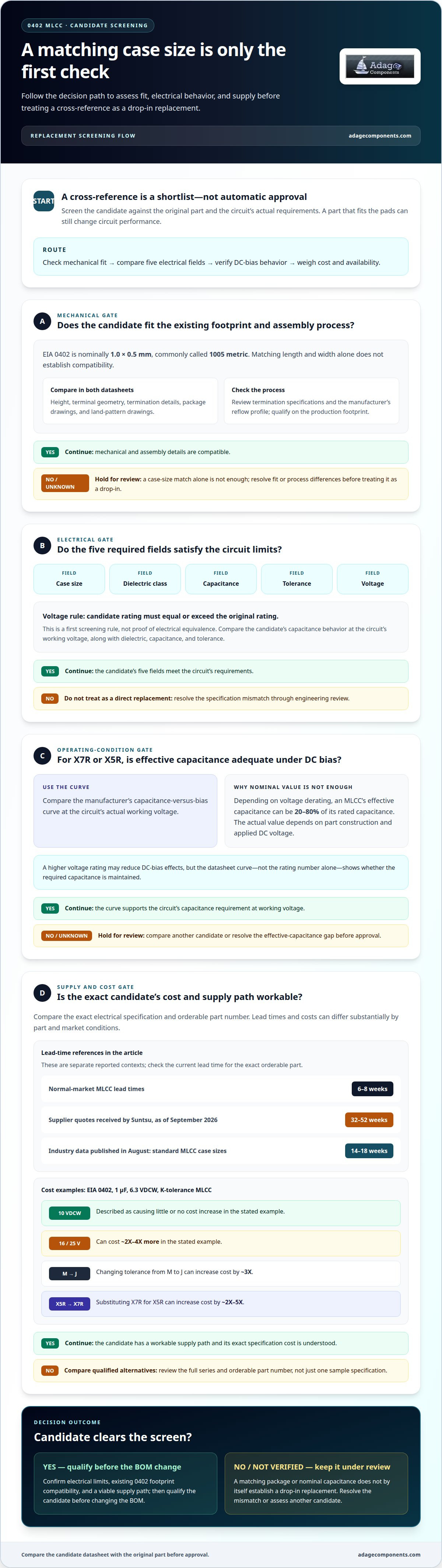
A 0402 MLCC isn't a direct replacement just because the case size matches. A reliable 0402 MLCC drop-in replacement cross reference must match five fields: case size, dielectric class, capacitance, tolerance and voltage. For X7R and X5R parts, also compare effective capacitance under DC bias at the working voltage.
That distinction matters when a part is costly or difficult to source: a substitute that fits the pads can still change circuit performance. You’ll learn how to assess electrical and layout compatibility, compare dielectric behavior and voltage ratings, and weigh cost and availability without treating a catalog match as automatic approval. This guide brings those checks together so you can identify candidates for engineering review and distinguish a true drop-in option from a design change.
Key Takeaways
- Compare candidate parts by total circuit suitability, not unit cost alone; shifts in voltage rating, tolerance, or dielectric can change the economics.
- A higher voltage rating can reduce DC-bias effects, but compare effective capacitance at the circuit’s operating voltage before approving a substitute.
- Temperature characteristics vary by dielectric class, so match the replacement to the circuit’s operating range and stability needs.
- A matching part number or nominal capacitance doesn’t guarantee a drop-in fit; a case-size change can require a PCB revision.
- Use manufacturer DC-bias curves to assess cross-brand X7R and X5R candidates rather than assuming package sizes behave alike.
Cost and availability considerations
A 0402 MLCC drop-in replacement cross-reference is a shortlist, not automatic approval. Compare case size, dielectric class, capacitance, tolerance, and voltage before weighing price or supply. A candidate that matches nominal capacitance but changes dielectric may alter filtering and effective capacitance. For high-volume SMT, evaluate the full series and its orderable part number, not just one sample specification.
Supply conditions can change the economics quickly. Normal-market MLCC lead times typically run 6 to 8 weeks, while supplier quotes received by Suntsu put lead times at 32 to 52 weeks as of September 2026. Industry data published in August put standard MLCC case-size lead times at 14 to 18 weeks. High-capacitance 0402 parts in the 10µF to 47µF range have limited availability, so compare qualified alternatives before a shortage affects production.
Cost depends on the exact electrical specification. For an EIA 0402, 1 μ F, 6.3V VDCW, K-tolerance MLCC, moving to a 10 VDCW variant is described as causing little or no cost increase. A 16 VDCW or 25 VDCW variant can cost ~2X-4X more. In the same example, changing M tolerance to J can increase cost by ~3X, while substituting X7R for X5R can increase it by ~2X-5X.
Which manufacturers offer 0402 MLCC drop-in replacement cross-reference tools? Manufacturer-specific selectors and cross-reference resources are the starting point; Murata is one manufacturer named in example part mappings. Treat any suggested alternate as a candidate, then compare its datasheet against the original.
What 0402 MLCC package dimensions, thickness, and termination details must match for a drop-in replacement? EIA 0402 is nominally 1.0 × 0.5 mm, commonly called 1005 metric. Compare the candidate’s height, terminal geometry, and termination details in both datasheets, because matching length and width alone doesn’t establish mechanical or assembly compatibility.
How can engineers verify 0402 MLCC footprint, solderability, and reflow compatibility before substitution? Compare package and land-pattern drawings, termination specifications, and the manufacturer’s reflow profile; then qualify the candidate on the production footprint. This catches solder-joint or process issues that a part-number cross-reference can miss.
Where can I find 0402 MLCC datasheets, lifecycle status, and manufacturer-approved alternate part numbers? Use the relevant manufacturer’s product page and part-number search for current datasheets, lifecycle notices, and approved alternate references. Record the exact series and full part number in the BOM review.
| Replacement option | Electrical match | Cost and availability | Best use |
|---|---|---|---|
| Same series, higher voltage | Retain capacitance, dielectric, and tolerance | 10 VDCW may add little or no cost in the stated example | When voltage margin is needed |
| Same series, different tolerance | Check circuit tolerance limits | J rather than M may increase cost ~3X | When tighter tolerance is required |
| Alternate series or manufacturer | Compare all five fields and the datasheet | Check current lead time and orderable status | When the original is constrained |
Choose the candidate that meets the circuit’s electrical limits, fits the existing 0402 footprint, and has a viable supply path, then qualify it before the BOM change.
Voltage-rating substitutions
A replacement MLCC’s voltage rating must equal or exceed the original component’s rating. That is the first screening rule, not proof of electrical equivalence. A higher rating can reduce the effect of voltage on capacitance, but the replacement’s dielectric, capacitance, and tolerance still matter. For a 0402 MLCC drop-in replacement cross reference, compare ratings alongside effective capacitance at the circuit’s working voltage.
Rated capacitance is measured under specified conditions. In operation, an MLCC’s effective capacitance can be 20-80% of its rated capacitance, depending on voltage derating. The actual value depends on the part’s construction and applied DC voltage. This voltage coefficient matters most when a circuit relies on a minimum capacitance for filtering, timing, or converter stability. A part with a higher voltage rating may retain more capacitance under bias, but its datasheet curve is the deciding evidence.
Consider an original 0402 capacitor rated for 6.3V in a circuit with a lower working voltage. A candidate rated at 10V meets the basic equal-or-higher rating rule. However, engineers still need to compare its capacitance-versus-bias curve at the actual operating voltage. A 25V option also clears the rating threshold, but the larger number alone doesn’t establish that it delivers the required capacitance or matches the original’s behavior.
Use a structured comparison for each candidate:
- Original rating: Record the part’s rated voltage and the circuit’s maximum operating voltage.
- Candidate rating: Exclude parts rated below the original; then compare voltage-bias curves.
- Effective capacitance: Confirm the value at working voltage, not just the nominal value.
- Series consistency: Compare the same manufacturer’s series where possible, because construction affects voltage behavior.
Keep package and design limits in view. A higher-rated 0402 part may preserve the PCB footprint, but its capacitance under bias can still differ. In the comparison of CC0402CRNPO9BN6R8 and CC0402BRNPO9BN8R0, both parts carry a 50 V rating. Equal voltage ratings do not by themselves prove a direct replacement; capacitance, tolerance, dielectric, and temperature characteristics must also align.
Technology changes need additional scrutiny. NbO capacitors with MnO2 electrodes are limited to a maximum rated voltage of 10V, so they aren’t candidates where the required rating exceeds that limit. For an MLCC sourcing review, map the operating voltage and required effective capacitance to the manufacturer’s datasheet curves before approving an alternate. The electronic component line card can help identify component categories for that comparison.
Dielectric and temperature-characteristic substitutions
A 0402 MLCC can match another part’s capacitance and voltage yet behave differently across temperature. Compare dielectric class, operating range, and capacitance variation before approving a substitute. Class 1 C0G/NP0 is designed for stability: its capacitance drift stays within 0 ±30 ppm/°C from -55°C to +125°C. Class 2 dielectrics such as X5R and X7R provide different temperature characteristics.
X5R MLCCs are specified for -55°C to +85°C. X7R parts operate from -55°C to +125°C, with capacitance variation up to ±15%. X8R MLCCs are specified to operate up to +150°C. These ranges are not interchangeable. For example, an X5R candidate in equipment that reaches temperatures above its specified upper limit fails the temperature-range comparison, even if its nominal capacitance matches.
Temperature codes also describe different allowed capacitance changes. X7T permits variation from +22% to -33% over temperature. A broader allowed swing can affect circuits that depend on stable capacitance for filtering, timing, or signal response. High-capacitance MLCC capacitance decreases at both high and low temperatures, so compare the capacitance value across the full operating range rather than relying only on its nominal room-temperature figure.
Use the manufacturer’s datasheet to assess each alternative against the design requirements:
- Identify the original dielectric: Record whether the part is C0G/NP0, X5R, X7R, X8R, or another class.
- Compare operating limits: Match the candidate’s stated temperature range to the application’s full operating range.
- Review variation: Compare the permitted capacitance change over temperature, not just the capacitance value at room temperature.
- Assess circuit sensitivity: Prioritize tighter stability when the component sets a tuned frequency or timing response.
A smaller case size or alternate series can also change available capacitance and temperature behavior. Don’t assume parts from different manufacturers share identical curves because their codes look similar. Check the specific series datasheet and confirm that the candidate maintains the required capacitance at operating temperatures. For a C0G/NP0 part, preserve its stability characteristics when the circuit depends on a predictable value; replacing it with a Class 2 alternative changes that behavior.
For example, the comparison of CC0402CRNPO9BN6R8 and CC0402BRNPO9BN8R0 lists a -55 to 125 °C temperature range for both, but the alternatives differ in nominal capacitance: 6.8 pF versus 8.0 pF. That change can affect tuning or RF response. Review temperature range, dielectric grade, capacitance, and circuit function together before treating either part as a direct replacement.
Sourcing and replacement mistakes
A sound substitution review separates mechanical fit, electrical performance, and sourcing risk. Key reliability risks include board-flexure cracking, a mismatched footprint, and voltage derating that reduces effective capacitance.
Cracking and flexure risks
Cracking and flexure are mechanical risks, unlike voltage derating, which affects electrical performance. A ceramic capacitor can crack when board flexure places stress on its body or solder joints. Case size is one factor in component selection: some manufacturers limit high-volume MLCC production to case sizes no larger than 1210 because of cracking risk. A replacement review should preserve the PCB footprint and account for the board’s mechanical conditions.
Voltage derating risks
Voltage derating changes available capacitance under applied DC voltage; it doesn’t alter the footprint or solve a flexure issue. An MLCC’s effective capacitance can be 20-80% of its rated capacitance, depending on voltage derating. A replacement with the same nominal capacitance can therefore provide a different value in operation. Compare manufacturer DC-bias curves at the circuit’s working voltage before accepting an alternate.
Package mismatches can make a proposed replacement unusable without a board change. For example, a 1210 pad cannot take a 0402 part; moving between these case sizes requires a PCB revision, not only a bill-of-materials edit. A cross-reference that lists both parts as alternatives doesn’t make them mechanically interchangeable. The footprint must match the existing land pattern for a true drop-in substitution.
- Footprint: Match the candidate’s EIA case size to the installed component and PCB pads.
- Application grade: Match the original grade or select a higher grade, never a lower one.
- Voltage rating: Keep the candidate’s rating equal to or higher than the original, then assess effective capacitance under bias.
- Volume: Review the exact manufacturer and series for production suitability and sourcing continuity.
These checks catch different failure modes. A 0402 part may fit the board but lose too much effective capacitance at operating voltage. A higher-rated component may meet the electrical requirement but still fail the mechanical fit check if its case size differs. Treat each factor independently rather than allowing a match on one specification to stand in for the others.
Before approving a BOM substitution, record the original part number, candidate series, case size, application grade, and voltage rating. Compare the manufacturer’s mechanical drawing and DC-bias data with the design requirements. This creates a traceable basis for engineering and procurement approval, and distinguishes a compatible replacement from a part that needs a PCB revision or further qualification.
DC-bias checks for X7R and X5R replacements
Nominal capacitance alone doesn’t show how an X7R or X5R MLCC behaves in a circuit. DC bias and temperature reduce effective capacitance, while dielectric aging can change the measured value over time. Compare the exact manufacturer’s data for the candidate, including its DC-bias curve, temperature characteristics, and aging specification.
How do DC bias, temperature, and aging affect effective capacitance in 0402 MLCC replacements? Applied DC voltage reduces capacitance in X7R and X5R parts, and temperature changes it further. Class 2 ceramic dielectrics also exhibit aging, so capacitance can drift over time; use the manufacturer’s stated conditions and aging data when assessing the circuit’s required value.
Compare the original and replacement at the circuit’s working voltage, not only at zero bias. For each part, locate the DC-bias curve in its datasheet and read the capacitance remaining at the intended voltage. Then compare the result with the minimum value the electronic design needs. Two 0402 components with identical nominal capacitance can have different curves because manufacturer, series, and internal construction differ.
Temperature must be considered alongside bias. X5R is specified for -55°C to +85°C, while X7R operates from -55°C to +125°C with capacitance variation up to ±15%. Those ranges describe temperature behavior, not the capacitance retained under an applied voltage. Review both sets of data for the actual operating conditions, including the circuit’s highest expected temperature and DC voltage.
- Match the test conditions: Compare candidate curves at the same DC voltage and temperature.
- Check the required minimum: Evaluate effective capacitance against the circuit’s filtering, timing, or decoupling needs.
- Review aging data: Use each manufacturer’s stated aging conditions and reference point when comparing initial and later measurements.
- Reassess package changes: For different case sizes, use the exact part’s curve; don’t assume package dimensions predict bias performance.
For automotive or other temperature-sensitive applications, assess the full operating envelope rather than relying on a single room-temperature test. If a replacement’s curve falls below the required capacitance at the working voltage, a matching nominal value won’t make it suitable. A different series or case size may change the curve, so evaluate the exact orderable component using its datasheet.
Document the original and candidate part numbers, working voltage, temperature conditions, and effective capacitance used in the decision. This creates a traceable comparison for engineering approval and BOM control. Use the electronic component line card to identify relevant component categories for your sourcing review.
Adage Components: Multilayer Ceramic Capacitors (MLCC)
Adage Components supports MLCC sourcing when cost, continuity, and quality assurance matter to your production plan. We connect you with authentic components through vetted manufacturers and partner suppliers, many franchised by top 100 distributors. Our sourcing approach supports ISO certification requirements and commercial and automotive grade components. We offer manufacturer pricing and OEM pricing, with the same advantages as buying from tier 1 distributors but at OEM pricing. Our international logistics program and growing state-of-the-art warehouse support short lead times and integration with your MRP system, helping coordinate delivery to your facility. For related resistor needs, we also offer Thick Film Chip Resistors, Thin Film Precision Resistors, and Carbon Film Resistors. Contact Adage Components to discuss your MLCC sourcing requirements.
Make the Next Replacement Decision Easier
A replacement decision should remain useful after the immediate supply issue has passed. Record the selected alternate, its manufacturer series, approved operating conditions, and engineering disposition in your controlled BOM workflow. This gives procurement a traceable basis for future sourcing decisions and keeps component approval tied to design requirements, not simply to whichever part is easiest to obtain.
Use a 0402 MLCC drop-in replacement cross reference as a qualification record, not a one-time parts lookup. Preserve the criteria behind the decision so the next lifecycle or supply review can distinguish an approved alternate from an unevaluated candidate. This supports consistent handoffs between engineering and procurement as product demand and component supply shift.
Adage Components can support your MLCC sourcing review and connect component requirements with procurement needs. If you’re planning a BOM review or sourcing plan, start a sourcing inquiry with Adage Components. Move forward with a clear record and a practical next step.
Frequently Asked Questions
Can it be replaced directly?
Yes, if the candidate meets the electrical requirements and fits the existing PCB footprint. A cross-reference for 0402 MLCC replacements is a starting point, not approval by itself. Check the complete part number and manufacturer datasheet, then confirm the candidate meets the design’s operating conditions. If the case size or termination geometry changes, the substitution may need layout or assembly review rather than a simple BOM update.
What Technical Specifications Must Be Matched When Cross-Referencing MLCC Drop-In Replacements?
Match the case size, dielectric class, capacitance, tolerance, and voltage rating. A 0402 MLCC drop-in replacement cross reference can help identify candidates, but manufacturer-specific data still distinguishes parts with similar headline specifications. Review effective capacitance under bias and temperature conditions, then compare the exact orderable part numbers and mechanical drawings. The replacement should meet the original application grade or a higher one.
What does 0402 mean for MLCC dimensions and how does it map to metric size 1005?
For an EIA MLCC, 0402 identifies a nominal body size of 1.0 × 0.5 mm and is commonly called 1005 metric. The naming systems use different conventions, so don’t assume “0402” means the same dimensions across every standard. Confirm the manufacturer’s drawing for height, termination, and tolerances. Those details matter for placement and solder-joint compatibility, even when nominal length and width match.
What electrical specifications must match when replacing a 0402 MLCC: capacitance, voltage, tolerance, and dielectric?
Match nominal capacitance and tolerance to the circuit’s permitted range, and select a voltage rating equal to or higher than the original. Preserve the dielectric when its temperature stability or bias response matters. Tolerance codes also carry specific limits: N is ±30%, M is ±20%, and K is ±10%. A tighter tolerance may affect cost and availability, so use the circuit’s acceptance limits to guide selection.
How do X7R, X5R, C0G, and other dielectric types compare for 0402 replacement parts?
C0G/NP0 suits applications that need stable capacitance, with drift within 0 ±30 ppm/°C from -55°C to +125°C. X5R operates from -55°C to +85°C, while X7R operates from -55°C to +125°C with variation up to ±15%. When using a 0402 MLCC drop-in replacement cross reference, compare dielectric behavior and temperature range against the circuit’s operating conditions, not code similarity alone.
What are typical prices and lead times for common 0402 MLCC replacement parts in the United States?
There’s no single typical price: cost depends on capacitance, voltage rating, tolerance, dielectric, and order volume. Lead times also vary by part and market conditions. Normal-market MLCC lead times typically run 6 to 8 weeks; industry data published in August put lead times for standard MLCC case sizes at 14 to 18 weeks. Treat those figures as planning context for evaluating the specific part and supply situation.
Disclaimer
Cross-referenced components needs to be confirmed by the client with either spec. sheet or samples or both.
Please note, we use AI to help us, information is verified to be correct but we can not guarantee 100% accuracy.


