

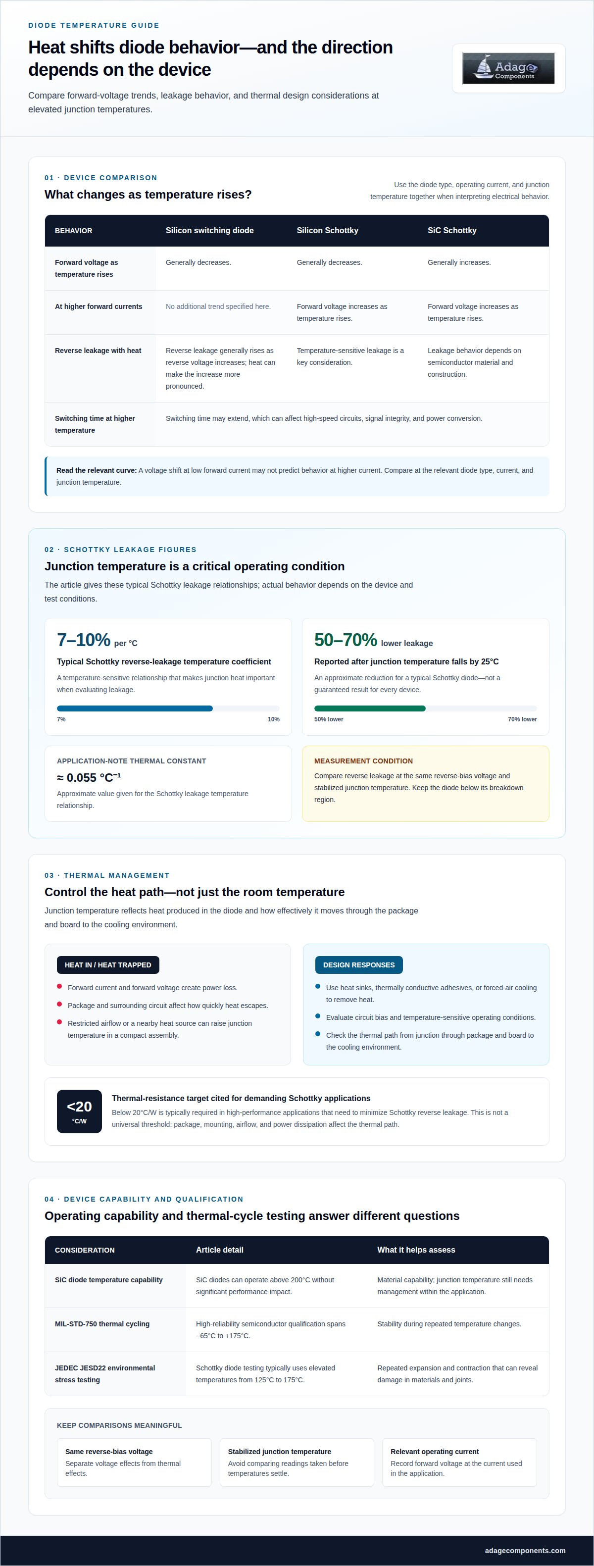
Heat can shorten a diode’s useful life even before it fails outright. As temperature rises, reverse leakage current increases; for Schottky diodes, the temperature coefficient typically ranges from 7% to 10% per degree Celsius. Silicon switching diodes also tend to show lower forward voltage at higher temperatures, while switching time may extend. This diode leakage current escalation at high operating temperatures can affect both circuit performance and long-term reliability.
It’s reasonable to ask whether a diode can handle its operating temperature. But leakage current, forward voltage, switching behavior, junction temperature, and aging all matter when assessing performance over time. Understanding how these factors interact helps you evaluate thermal risk and interpret electrical measurements accurately.
This article explains how temperature affects diode behavior, how thermal management can control junction heat, and why prolonged exposure may reduce lifespan. It also compares leakage trends across diode types and outlines practical measurement considerations for design and component evaluation.
Key Takeaways
- Track reverse leakage alongside forward voltage as junction temperature changes; one reading alone may miss a developing thermal issue.
- Account for diode material and operating current when evaluating forward voltage and switching performance at elevated temperatures.
- Manage junction heat with appropriate thermal design, since reducing operating temperature can help limit leakage and reliability risks.
- Assess lifespan against sustained heat exposure and thermal cycling, not just short-term electrical performance.
- Compare leakage measurements under consistent temperature and test conditions to make component evaluations more meaningful.
1. Temperature effects on forward voltage drop, reverse leakage current, and switching speed
Reverse-bias voltage affects leakage: as reverse voltage increases, reverse leakage generally rises, with a more pronounced increase at high temperatures. Keep the diode below its breakdown region, where current can climb sharply. Compare leakage at the same reverse voltage and temperature to distinguish voltage effects from thermal effects.
Temperature has a strong effect on Schottky diode leakage. Its reverse-leakage temperature coefficient typically ranges from 7% to 10% per degree Celsius. A typical Schottky diode can show approximately 50% to 70% lower reverse leakage after its junction temperature falls by 25°C. These figures make junction temperature a critical operating condition, not merely an ambient measurement.
Two temperature-dependent mechanisms help explain this behavior. Heating gives donor electrons more energy, making excitation into conductive states easier and increasing leakage. At the same time, stronger atomic lattice vibrations hinder electron diffusion. The balance between these effects depends on the diode’s semiconductor material and construction. For Schottky leakage, an application note gives an approximate thermal constant of 0.055 °C⁻¹ for the temperature relationship.
Forward voltage also changes with heat, but the direction depends on diode type and operating current. A silicon switching diode generally has a lower forward voltage as temperature rises. Silicon Schottky barrier diodes also generally show lower forward voltage, while silicon carbide (SiC) Schottky barrier diodes generally show higher forward voltage. At higher forward currents, however, the forward voltage of both silicon and SiC Schottky barrier diodes increases as temperature rises.
This distinction matters when comparing datasheet curves or evaluating a circuit at different loads. For example, a voltage shift measured at low forward current may not predict behavior at higher current. Use the curve for the relevant diode type, forward current, and junction temperature rather than treating one forward-voltage value as universal.
Switching performance can also change: higher temperatures may extend diode switching time and affect high-speed circuits. Even a small change can matter when switching timing affects signal integrity or power conversion. Include the diode’s actual operating temperature and switching conditions in design evaluation alongside forward voltage and leakage.
For a useful electrical comparison, control the test conditions. Measure reverse leakage at a consistent reverse-bias voltage, allow the junction temperature to stabilize, and record forward voltage at the relevant current. Repeat across the expected operating temperatures. This makes diode leakage current escalation at high operating temperatures easier to distinguish from measurement variation and helps designers account for temperature-dependent characteristics.
2. Thermal management and junction temperature
Junction temperature, not room temperature alone, determines the heat inside a diode. Forward current and forward voltage create power loss, while the package and surrounding circuit affect how quickly heat escapes. In a compact assembly, restricted airflow or a nearby heat source can raise junction temperature even when ambient conditions seem controlled. Estimate the thermal path from the junction through the package and board to the cooling environment.
To reduce or compensate for temperature-dependent leakage, lower the junction temperature and design the circuit around the diode’s leakage behavior across its operating range. Heat sinks, thermally conductive adhesives, and forced-air cooling can remove heat. Also evaluate circuit bias and temperature-sensitive operating conditions.
For high-performance applications that need to minimize Schottky reverse leakage, thermal resistance below 20°C/W is typically required. This is a design target, not a universal threshold: package, mounting, airflow, and power dissipation affect the thermal path. A heat sink cannot compensate for poor contact, and forced air may have limited effect if heat cannot transfer efficiently from the diode package.
Packaging matters too. Materials used in high-temperature diode packages should conduct heat effectively and resist thermal expansion. Silicon diodes are more susceptible to thermal runaway than SiC diodes, so thermal feedback deserves careful attention. As a diode warms, its electrical behavior can increase heat generation, depending on the circuit and device characteristics. SiC diodes can operate above 200°C without significant performance impact, but that material capability does not remove the need to manage junction temperature within the application.
Thermal cycling tests assess stability during repeated temperature changes. MIL-STD-750 thermal cycling for high-reliability semiconductor qualification spans −65°C to +175°C. JEDEC JESD22 environmental stress testing for Schottky diodes typically uses elevated temperatures ranging from 125°C to 175°C. Repeated expansion and contraction can reveal physical damage in materials and joints that a steady-temperature test may not expose.
Use test results to evaluate the complete thermal design, not just the diode’s initial electrical reading. Confirm that the mounting method, cooling arrangement, and surrounding components match the evaluated setup. Thermal cycling can expose an assembly weakness even when a diode performs normally at a stable temperature. Compare electrical behavior before and after cycling to identify changes linked to thermal stress.
For component planning, compare diode options alongside their thermal requirements using the diode component line card. Match the device to the circuit’s expected heat load, cooling method, and operating conditions.
3. Diode lifespan under prolonged high-temperature operation
High-temperature leakage can raise standby current, shift the bias of a high-impedance node, and reduce circuit operating margin. In a power path, additional current can also increase heat, adding stress to the diode and nearby components. Prolonged operation at high temperatures can shorten diode lifespan through accelerated semiconductor aging and deterioration of metal solder joints.
Semiconductor aging changes device behavior over time rather than causing only an immediate electrical shift. A diode exposed to sustained heat may gradually depart from its earlier leakage or forward-voltage readings. In a control circuit, for example, increased leakage can alter the voltage at a sensing node. That drift can affect downstream switching decisions even before the diode stops conducting normally.
Metal solder joints create a separate reliability concern. Heat stresses the connection between the diode and its assembly, while weakened or degraded solder can compromise electrical and thermal paths. A degraded connection may cause intermittent behavior or localized heating. These effects can compound: poorer heat transfer raises junction temperature, while elevated temperature accelerates stress on the assembly.
Long-term aging tests assess diode reliability by holding devices in a constant, high-temperature environment. A useful evaluation compares electrical measurements before exposure, during scheduled checks, and after the test. Track reverse leakage, forward voltage, and changes in switching behavior under consistent conditions. Stable test conditions help distinguish gradual aging from measurement differences caused by temperature or setup.
For circuit assessment, relate the measured trend to the diode’s role. In a reverse-biased sensing path, rising leakage may distort a small signal. In a rectifier application, a change in leakage can add unwanted current during the non-conducting portion of operation. Review surrounding components too, since a resistor, capacitor, or control input may respond differently to the same leakage shift.
Use a repeatable review process to make lifecycle decisions. Record the diode’s operating temperature, reverse-bias condition, load, and measurement setup. Compare results across test intervals, then check whether the circuit still meets its intended operating limits. A single passing reading cannot describe long-term aging; the trend shows whether electrical drift is developing during sustained exposure.
Designers can reduce lifecycle risk by limiting unnecessary heat and selecting a diode whose electrical behavior suits the application. Evaluate leakage under the circuit’s actual reverse-bias conditions, then consider how rising leakage would affect sensitive nodes or power budgets. For equipment exposed to sustained heat, include the diode and its soldered connections in reliability reviews, not just system-level functional checks.
5. How do Schottky, silicon, and germanium diode leakage currents compare at high temperatures?
Material names offer a starting point, not a complete leakage ranking. Schottky, silicon pn-junction, and germanium diodes differ in construction and electrical behavior. Compare the specific device’s reverse-current data at the same reverse voltage and junction temperature. Comparisons made under different test conditions can confuse device differences with changes caused by temperature or bias.
Schottky diodes are especially sensitive to junction temperature. Their reverse leakage typically rises rapidly as temperature increases, making thermal conditions important in circuits with reverse-biased Schottky devices. Silicon pn-junction diodes show the same general temperature-related tendency described for Schottky barrier diodes. This shared direction does not mean their leakage values match; device construction and test conditions still matter.
Silicon-based diodes can experience sharply deteriorating performance when temperatures exceed 150°C. Treat that threshold as a warning for evaluation, not as a universal failure point for every silicon diode. The relevant evidence is the device’s electrical behavior at its actual operating temperature. Review leakage alongside other specifications, since a diode’s performance includes more than reverse current alone.
Apply the same disciplined comparison to germanium diodes. Don’t assume their leakage relative to silicon or Schottky devices from the material name alone. Identify the exact diode type and compare its specified reverse current under matching conditions. For example, a germanium device measured at one reverse voltage cannot be fairly ranked against a Schottky diode measured at another.
Use this comparison sequence to make the data useful:
- Identify whether each device is Schottky, silicon pn-junction, or germanium.
- Match reverse-bias voltage and junction temperature for every comparison.
- Record leakage values and test conditions from each device’s electrical data.
- Repeat measurements at the temperatures relevant to the application.
This method separates the temperature trend from differences in test setup. It also helps reveal whether a particular diode’s leakage affects the circuit’s reverse-biased state, especially where the circuit depends on a high-impedance input or low standby current. Compare like with like before choosing a device for that function.
For high-temperature designs, evaluate semiconductor type alongside the device’s complete operating conditions. A Schottky diode may suit a circuit for one reason, while its leakage sensitivity requires attention in another. Silicon pn-junction behavior also changes with heat, and germanium needs device-specific assessment. Choose based on matched electrical data, thermal conditions, and circuit requirements, not a material-only ranking.
Keep the comparison tied to the application’s operating envelope. If a circuit approaches 150°C, examine the silicon device’s behavior closely and assess whether its leakage affects operation. For Schottky or germanium options, use the same test conditions and evaluate the actual circuit impact. This converts a broad material comparison into a defensible component decision.
5. What are typical diode leakage current values at different junction temperatures?
There isn’t one leakage-current value that applies to every diode at a given junction temperature. Schottky, silicon pn-junction, and germanium diodes can behave differently, and reverse-bias voltage also affects measured current. Use the specific device’s electrical data and compare values under matching conditions.
For a useful temperature comparison, record reverse current at each junction temperature alongside the applied reverse voltage. Keep the diode type, measurement setup, and stabilization procedure consistent. For example, comparing a Schottky diode at one bias voltage with a silicon diode at another won’t isolate the effect of temperature.
Read the device’s leakage specification alongside its test conditions. A value measured at a stated temperature and reverse voltage describes that condition, not every operating point. Evaluate expected current at another temperature using the device’s temperature characteristics. Schottky diode reverse leakage is particularly temperature-sensitive, so even a small change in junction conditions can affect the circuit’s leakage budget.
Build a temperature profile from the application rather than relying on a single room-temperature measurement. Include the expected junction-temperature range, reverse-bias conditions, and the diode’s role. In a high-impedance sensing path, leakage can influence the signal node. In a rectifier circuit, it contributes current during reverse bias. These examples show why the same current reading can matter differently across applications.
Use this practical sequence when reviewing data:
- Identify the diode construction and part-specific leakage specification.
- Record junction temperature and reverse-bias voltage for each reading.
- Compare measurements taken after the device reaches a stable temperature.
- Assess whether the observed current affects the circuit’s operating limits.
Temperature trends provide useful context even when absolute current values differ across devices. Leakage generally rises as temperature increases, while the rate and circuit impact depend on diode construction and operating conditions. Silicon pn-junction diodes share the general temperature-related increase described for Schottky barrier diodes. That trend helps frame an evaluation, but it does not replace the individual device’s data.
For a design review, plot measured reverse current against junction temperature at the application’s reverse-bias voltage. Check the curve against input impedance, standby-current targets, or other relevant circuit constraints. Repeat the measurement with the same setup if readings vary. This approach turns datasheet values and bench results into a practical operating profile rather than treating a single “typical” number as universal.
Compare available diode component options against the leakage conditions your circuit must meet, then use the relevant device data to evaluate each candidate.
Adage Components: Thick Film Chip Resistors
Adage Components supports component planning with Thick Film Chip Resistors, Thin Film Precision Resistors, Carbon Film Resistors, and MELF Resistors. We help customers source authentic components through vetted manufacturers and partner suppliers, many franchised by top 100 distributors. Our commercial and automotive grade component support combines manufacturer pricing and OEM pricing with the advantages of tier 1 distribution.
We coordinate international logistics and short lead times, supported by a growing state-of-the-art warehouse. This supply approach is designed to integrate with your MRP system and deliver components to your facility in real time, on time. For diode sourcing, our Diode OEM Partner holds ISO 9001, IATF 16949, ISO 14001, and QC080000 certifications. These credentials apply to that partner, not to Adage Components as a whole.
Contact Adage Components to discuss your component requirements.
Make the next design decision with operating conditions in view
Planning for diode leakage current escalation at high operating temperatures means treating component validation as an operating-condition decision, not a datasheet checkbox. Define the temperature and reverse-bias conditions your circuit must handle, then use them to guide component review and qualification. This gives engineering and procurement teams a shared basis for evaluating parts against the application.
Carry that discipline into your next sourcing decision. Align the diode requirement with the circuit’s intended use, then review available options against the relevant electrical data. Adage Components can support your diode sourcing needs as you move from technical evaluation to component selection.
Review Adage Components’ diode line card and take the next step toward a component decision grounded in your application. Clear requirements make the path forward more practical, and your team can move ahead with greater confidence.
Frequently Asked Questions
How does diode reverse leakage current change with temperature?
Reverse leakage generally rises as the diode’s junction temperature increases, with the trend depending on device construction and reverse-bias voltage. For Schottky diodes, the typical leakage-current temperature coefficient is 7% to 10% per degree Celsius. Compare readings only under matching test conditions. Record reverse voltage and stabilized junction temperature with each measurement, since an ambient-temperature reading cannot substitute for junction-temperature data.
What causes diode leakage current to increase at high temperatures?
Heat gives donor electrons more energy, making it easier for them to enter conductive states and contribute to current. Heating also intensifies atomic lattice vibrations, which hinder electron diffusion. These mechanisms affect leakage differently across semiconductor materials and diode constructions. For example, Schottky devices are particularly sensitive to junction temperature, so interpret their leakage measurements alongside the device’s material and reverse-bias conditions.
What is the maximum operating junction temperature for common diodes?
There is no single maximum junction temperature for all common diodes; the applicable limit depends on the specific device’s rating. Silicon-based diodes can experience sharply deteriorating performance above 150°C, while silicon carbide diodes can operate above 200°C without significant performance impact. These figures describe performance behavior, not a universal maximum rating. Use the selected diode’s specified operating limits when setting the circuit’s thermal design target.
How can diode leakage current be measured accurately at elevated temperatures?
Use a controlled thermal setup, apply a known reverse-bias voltage, and measure current only after the diode reaches a stable junction temperature. A low-current source-measure instrument and guarded fixture can help reduce measurement error from the test setup. Keep wiring, voltage, and instrument range consistent across readings. Also measure fixture leakage separately, because unintended current paths can distort small diode-leakage readings.
Disclaimer
Cross-referenced components needs to be confirmed by the client with either spec. sheet or samples or both.
Please note, we use AI to help us, information is verified to be correct but we can not guarantee 100% accuracy.


