

A larger package doesn’t automatically make a resistor safe at its full rated power. The SMD thick film resistor power derating guidelines start with the component’s rated power and operating temperature: typical 0603 parts are rated at 1/10-1/8 W, while 2512 parts are typically rated at 1-2 W. Above the reference temperature, commonly 70 °C, allowable power falls according to the resistor’s derating curve.
Package size is a useful starting point, but it is only one part of the design decision. Ambient temperature, heat flow through the PCB, resistance value, and maximum working voltage can each limit safe operation before the resistor reaches its rated power.
This guide compares typical power ratings across common SMD packages, explains how to calculate derated power and voltage limits, and shows how PCB layout affects thermal performance. Use these comparisons to narrow your options, then check the selected resistor’s datasheet against your actual operating conditions.
Key Takeaways
- Use package power ratings as a starting point, then compare the resistor’s datasheet limits with your actual operating conditions.
- Account for temperature derating before setting a safe power target; a resistor’s allowable dissipation decreases as operating temperature rises.
- Review PCB copper balance and thermal paths because layout can affect heat dissipation and mounting reliability.
- Check both power and maximum-voltage limits. The lower limit determines the resistor’s safe operating point.
- Choose thick film for cost-effective general-purpose needs, and compare resistor technologies when precision, drift, or noise is a critical design factor.
SMD resistor package sizes and typical power ratings
Excess heat can shift a thick-film resistor’s resistance and accelerate material aging. Severe overheating may damage the resistive layer or terminations, resulting in unstable readings or an open circuit. Keep dissipation within the package’s temperature-dependent rating.
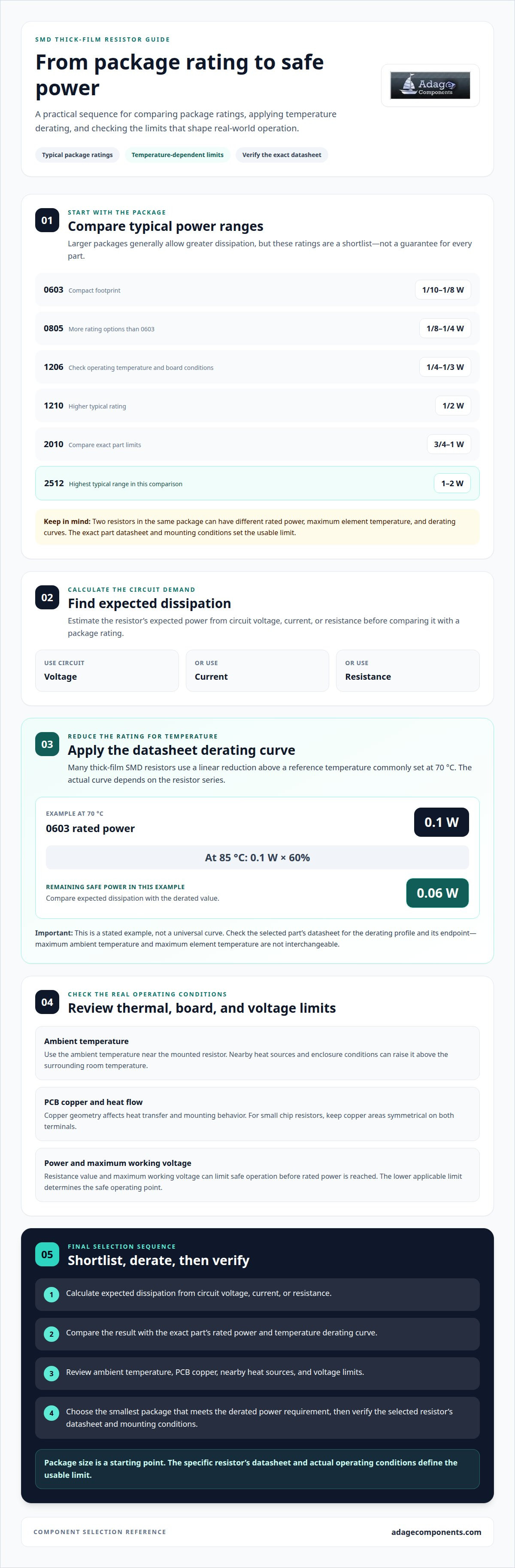
Package size gives an initial comparison, not a universal performance guarantee. Typical 0603 SMD resistors are rated at 1/10-1/8 W, while 0805 parts are rated at 1/8-1/4 W. A 1206 package commonly handles 1/4-1/3 W, and a 1210 commonly handles 1/2 W. Larger footprints generally allow greater power dissipation, but construction and datasheet conditions still matter.
| Package | Typical power rating | Selection consideration |
|---|---|---|
| 0603 | 1/10-1/8 W | Compact footprint; lower power range |
| 0805 | 1/8-1/4 W | More rating options than 0603 |
| 1206 | 1/4-1/3 W | Check operating temperature and board conditions |
| 1210 | 1/2 W | Higher typical rating in a larger package |
| 2010 | 3/4-1 W | Compare exact part limits |
| 2512 | 1-2 W | Highest typical range in this comparison |
These typical ratings help shortlist parts, but the exact resistor datasheet sets the usable limit. Two resistors in the same package can have different rated power, maximum element temperature, and derating curves. A 1206 part rated at 1/3 W, for example, does not make every 1206 resistor suitable for that dissipation. Match the specific part number and its mounting conditions to the circuit.
Use this sequence to select a practical rating:
- Calculate the resistor’s expected dissipation from circuit voltage, current, or resistance.
- Compare that value with the exact part’s rated power and derating curve.
- Review ambient temperature, PCB copper, and nearby heat sources before finalizing the package.
A package with a higher nominal rating can provide more capacity, but footprint alone cannot resolve thermal limits. For instance, a 2512 rated at 1-2 W still needs adequate heat transfer and operation within its datasheet limits. Apply the SMD thick film resistor power derating guidelines to the specific component, rather than selecting from package size alone. This approach helps align power rating, board space, and expected operating conditions.
Choose the smallest package that meets the circuit’s calculated power dissipation after temperature derating, then verify its voltage and thermal limits. When comparing close options, use the individual part’s datasheet rather than a typical package-level range.
Ambient temperature and safe operating power
There’s no single universal derating curve: many thick-film SMD resistors use a linear reduction above 70 °C. The exact curve depends on the resistor’s datasheet and its specified temperature limits.
Ambient-Temperature Operating Power
Ambient temperature affects how much of a resistor’s rated power remains available. Ratings are often specified at a reference ambient temperature of 70 °C, then reduced as temperature rises. This differs from nominal package power, which describes the rating at stated conditions rather than the power available in every environment. Use the ambient around the mounted component when assessing operating conditions.
For example, a 0603 resistor rated at 0.1 W at 70 °C has less available power at 85 °C in the example below. Nearby heat sources and enclosure conditions can raise local ambient temperature above the surrounding room temperature. Evaluate the resistor in its actual operating environment, not from a room-temperature assumption alone.
Standard Derating Curve
A common derating curve allows rated power up to a reference temperature, then reduces it linearly toward zero at the series’ maximum ambient or element temperature. This is a general pattern, not a curve shared by every SMD resistor. The selected part’s datasheet specifies the applicable limit and derating profile.
In the stated example, a 0603 resistor rated at 0.1 W at 70 °C is derated to 60% at an ambient temperature of 85 °C. Its safe power is then 0.06 W. The calculation is 0.1 W × 0.60. Apply the derating percentage to the rated power, rather than treating the original rating as available unchanged.
Use this sequence to assess a design:
- Find the rated power and reference temperature in the resistor datasheet.
- Determine the expected ambient temperature near the mounted component.
- Read the derating curve at that temperature and calculate the remaining power.
- Compare the result with the resistor’s expected circuit dissipation.
For operation above about 70 °C, reduce assumed power unless the datasheet specifies otherwise. The curve’s endpoint matters: some series define the limit by maximum ambient temperature, while others use an element-temperature limit. Don’t substitute one limit for the other. Likewise, don’t extend a straight-line estimate beyond the range shown in the datasheet.
At 85 °C, the example’s 0.06 W limit provides the design comparison point. If expected dissipation exceeds it, reduce circuit loading or select a resistor whose specified curve supports the required operating conditions. Review the applicable resistor data in the resistor component linecard as part of component selection.
PCB layout and thermal balance
The PCB footprint affects heat transfer and mounting behavior. Copper geometry around each terminal can influence both, so review the land pattern alongside the resistor’s thermal limits.
For small chip resistors, keep copper areas symmetrical on both terminals. This is especially important for sizes 0201-0603, where unequal wetting forces can contribute to tombstoning during soldering. A balanced footprint helps the part heat and wet more evenly across its two ends. Follow the selected resistor’s recommended land pattern, then compare both pads for similar shape and surrounding copper.
Thermal behavior also depends on the copper connected to each terminal. A large copper area on one side and a restricted trace on the other create different heat paths, potentially affecting local temperature and soldering behavior. More copper does not always produce a better result. Assess the complete footprint, nearby copper, and board arrangement together.
Review the layout in this order:
- Confirm the footprint matches the selected resistor package and recommended land pattern.
- Compare copper area and trace connections at both terminals.
- Look for nearby heat sources that may warm the resistor or one terminal.
- Assess the assembled board, not only the isolated footprint, when reviewing thermal paths.
Placement matters because adjacent components can change the local thermal environment. A resistor beside a heat-generating part may experience different conditions from an identical resistor elsewhere on the same PCB. Review nearby components, spacing, and copper routing for uneven heat paths. Base the assessment on both the package datasheet and the actual board geometry.
For example, a 0603 resistor with one terminal connected to a broad copper region and the other to a narrow trace has visibly unequal surroundings. Compare the terminal areas in the PCB layout before release. If the pads differ substantially, revise the copper arrangement where the circuit permits. This also helps reduce tombstoning risk for small sizes, particularly 0201-0603.
Include board-level thermal behavior in the resistor selection process. The datasheet rating applies under specified conditions, while the PCB determines how those conditions relate to the assembled design. Review the land pattern, nearby components, copper balance, and operating environment together. Considering these factors gives engineers a more realistic basis for evaluating thermal performance than footprint size alone.
Power and voltage-limit calculations
Power and voltage are separate limits for an SMD resistor. Calculate dissipation under circuit operating conditions, then compare the voltage across the resistor with its maximum working voltage. The first limit reached governs the design. A resistor can remain below its power rating while exceeding its voltage limit, particularly at high resistance values.
For a resistor with voltage across it, calculate power using P = V²/R. To calculate the voltage allowed by a power limit, rearrange the equation: V = √(P × R). Here, P is power in watts, V is voltage, and R is resistance in ohms. Keep units consistent.
Consider a 10 kΩ resistor rated at 0.1 W. Its power-based maximum continuous voltage is approximately 31.6 V. If derating reduces available power to 0.06 W, the recalculated maximum is approximately 24.5 V. The resistor’s safe operating voltage has fallen even though its resistance remains unchanged. Use the derated power in the equation, not the original rating.
That calculation does not replace the resistor’s maximum-voltage specification. Typical maximum voltage ranges are 50-75 V for 0603 SMD resistors and 100-150 V for 0805 SMD resistors. These package-level ranges are comparison points, not substitutes for a specific part’s datasheet. A calculated power limit can be lower than the component’s voltage rating, as in the 10 kΩ example.
Check the design in sequence:
- Determine the maximum continuous voltage across the resistor.
- Calculate dissipation using voltage and resistance, or current and resistance.
- Apply the power available at the operating temperature.
- Calculate the power-based voltage limit using derated power.
- Compare that result with the part’s maximum-voltage rating.
For a 0603 design operating near its typical 50-75 V maximum-voltage range, the exact resistor datasheet remains decisive. Resistance, available power, and the specified voltage limit jointly determine the permissible operating point. Apply temperature derating before comparing voltage, since reduced power also lowers the voltage allowed by V = √(P × R). For repetitive or changing operating conditions, assess the highest continuous voltage and resulting dissipation, rather than relying on nominal values alone.
Record both checks when selecting a component: calculated power under operating conditions and the voltage limit for the exact part. If either exceeds its allowable value, choose a suitably rated resistor or revise the circuit conditions. This avoids overlooking the independent voltage constraint in a power-only calculation.
Thick-film power handling
Each resistor series has its own datasheet derating curve, reference temperature, and thermal limits. For pulse loading, also assess pulse duration and repetition alongside average power, since steady-state derating alone does not describe transient stress.
Manufacturer Derating Guidelines
A manufacturer’s derating curve specifies the usable continuous power across temperature for a particular resistor series. Curves may vary with rated power, maximum temperature, and construction. Compare the exact part datasheets rather than assuming one curve applies to every thick-film chip resistor.
Thick-film resistors generally handle more power than thin-film resistors in the same footprint. However, limits remain series-specific: check the reference temperature, maximum ambient or element temperature, and power curve. Apply the selected part’s curve to its operating conditions, then compare its resulting continuous-power allowance with circuit dissipation.
Pulse-Power Considerations
Pulse capability concerns short-duration loading, unlike a continuous-power rating. Thick-film resistors have excellent surge and pulse tolerance compared with thin-film resistors, but the selected part’s pulse limits still apply. Evaluate pulse duration, repetition, and average power using the manufacturer’s pulse data.
Do not treat peak pulse power as continuous power when a design includes brief surges. Repeated pulses can add heat, while a single transient stresses the resistive element differently. Check pulse conditions and long-term average dissipation. A continuous derating curve alone cannot establish safe pulse operation.
Construction also affects pulse handling. A thick-film design without laser trimming tracks can increase pulse-load capability by 2 to 3 times. This is a design-dependent comparison, not a blanket multiplier for every component. Use the specific manufacturer’s pulse ratings and construction details when selecting a part for surge exposure.
Use this review sequence for power handling:
- Identify the exact resistor series and its continuous derating curve.
- Compare continuous dissipation with allowable power at operating temperature.
- Record pulse duration, repetition pattern, and peak loading.
- Compare pulse conditions with the part’s applicable pulse-load data.
- Assess average heating from repeated pulses alongside steady-state dissipation.
For example, a circuit with low average dissipation can still impose demanding short pulses. Conversely, a strong single-pulse rating doesn’t establish suitability for repeated events. Treat continuous power and pulse capability as separate criteria, then ensure both match the circuit’s actual loading. Compare thick-film resistor component options as you narrow the design selection.
Adage Components: Thick Film Chip Resistors
Adage Components offers Thick Film Chip Resistors for OEMs and electronic manufacturers seeking authentic components and manufacturer pricing. We provide OEM pricing with the same advantages as buying from tier 1 distributors, alongside one of the best costs in the industry. Our partner suppliers include many franchised by top 100 distributors, and we support commercial and automotive-grade components.
For procurement teams balancing cost and supply-chain integrity, Adage Components works with vetted manufacturers and conducts manufacturing audits to support quality standards and certifications. Our international logistics program and growing state-of-the-art warehouse support short lead times and coordination with your MRP system, helping products arrive at your facility in real time, on time.
Contact Adage Components to discuss resistor sourcing for your requirements.
Put Your Resistor Selection into Design Review
Make resistor selection a documented part of your next design review. Apply the SMD thick film resistor power derating guidelines to your circuit’s actual operating conditions, then record the selected component and the limits behind the decision. This gives engineering and procurement a clear basis for assessing substitutions and maintaining consistent component requirements across a bill of materials.
Adage Components offers Thick Film Chip Resistors, Thin Film Precision Resistors, and Carbon Film Resistors for different design priorities. Before finalizing your choice, match the resistor category to the application’s requirements, including precision and operating conditions.
To explore resistor options for your design, review Adage Components’ resistor linecard. A clear selection process helps move your next design forward with confidence.
Frequently Asked Questions
How does allowable resistor power change with ambient temperature?
Allowable power decreases as the resistor’s local operating temperature rises above the datasheet reference point. Evaluate the component on the assembled board under its highest expected load. Enclosure airflow, adjacent components, and board position can make the area around the resistor hotter than a general board measurement indicates. Measure near the resistor during representative operation, then apply the series’ derating data to that local temperature.
At what temperature do thick film chip resistors begin derating from rated power?
The derating point is the reference temperature specified for the resistor series; there is no single threshold for every thick-film chip resistor. Use the datasheet’s transition point to determine when usable power must be reduced. Do not infer it from the package code. If operating conditions exceed that point, apply the selected series’ curve rather than assuming the nominal rating remains available.
How does PCB pad size and copper area affect SMD resistor power dissipation?
Pad and copper geometry affect how heat spreads from the mounted resistor into the board. A custom footprint may perform differently from the manufacturer’s recommended land pattern, so do not assume its thermal behavior is identical. Review the PCB copper connected to both terminals and assess the assembled design, especially if layout changes alter pad dimensions or nearby copper routing.
What is the difference between resistor rated power and maximum working voltage?
Rated power is a thermal dissipation limit; maximum working voltage is an electrical stress limit. A circuit may stay within its power allowance while exceeding the permitted voltage across the resistor. In a high-resistance divider, for example, check the voltage across each resistor, not just the total divider dissipation. Assess transient conditions separately against the applicable component specifications.
What are typical power ratings and derating limits for 0201, 0402, 0603, 0805, and 1206 resistors?
Typical ratings and derating limits depend on the manufacturer and resistor series, so package code alone cannot provide a universal value. The article’s package comparison provides typical ranges for 0603, 0805, and 1206; for 0201 and 0402, use the specific part datasheet. Compare its power rating and derating curve under the intended mounting and operating conditions before finalizing the footprint.
What safety margin should be used when selecting an SMD thick film resistor?
There is no single safety margin for every design. Set required headroom according to the circuit’s worst-case load, component tolerances, and expected variation in operating conditions. Document the calculation assumptions so reviewers can assess them consistently. The margin should keep the selected part within its specified limits across the application’s required operating range.
How do board temperature and nearby heat sources affect resistor derating?
Nearby components can create localized temperatures that differ from the board’s general temperature. Review the resistor in operating states when adjacent power devices are active, as simultaneous loading may change the local environment. On a prototype, measure near the resistor after the board reaches representative operating conditions, then compare the result with the selected part’s datasheet limits.
Disclaimer
Cross-referenced components needs to be confirmed by the client with either spec. sheet or samples or both.
Please note, we use AI to help us, information is verified to be correct but we can not guarantee 100% accuracy.


