

The closest resistance value isn’t enough to make an alternative a safe drop-in. A drop-in testing protocol for alternative thin film resistors should compare electrical performance, failure risks, and application conditions, then qualify the part against the relevant requirements in IEC 60115 and IECQ-CECC. For pulse loads, assess the datasheet rating alongside IEC 61000 4 5 surge evaluation where applicable.
A replacement should match the original part’s resistance and fit the same footprint, but those checks alone are not enough. Temperature behavior, load life, moisture-related corrosion, and pulse response can also affect performance in the finished design. This guide explains how to screen these risks, choose relevant reliability checks, and use qualification standards to structure a practical comparison. A criteria table and decision guide help engineering and procurement teams assess alternatives against the application’s operating conditions.
Key Takeaways
- Identify moisture-related corrosion and other failure risks that can affect long-term resistor stability.
- Assess qualification standards in context, then align reliability checks with the component’s intended application.
- Compare package, resistance, and operating behavior to determine whether a candidate is genuinely interchangeable.
- Evaluate noise, voltage coefficient, and power rating against the demands of the circuit.
- Include solderability and reflow compatibility in the evaluation to reduce assembly-related substitution risk.
Failure modes and reliability
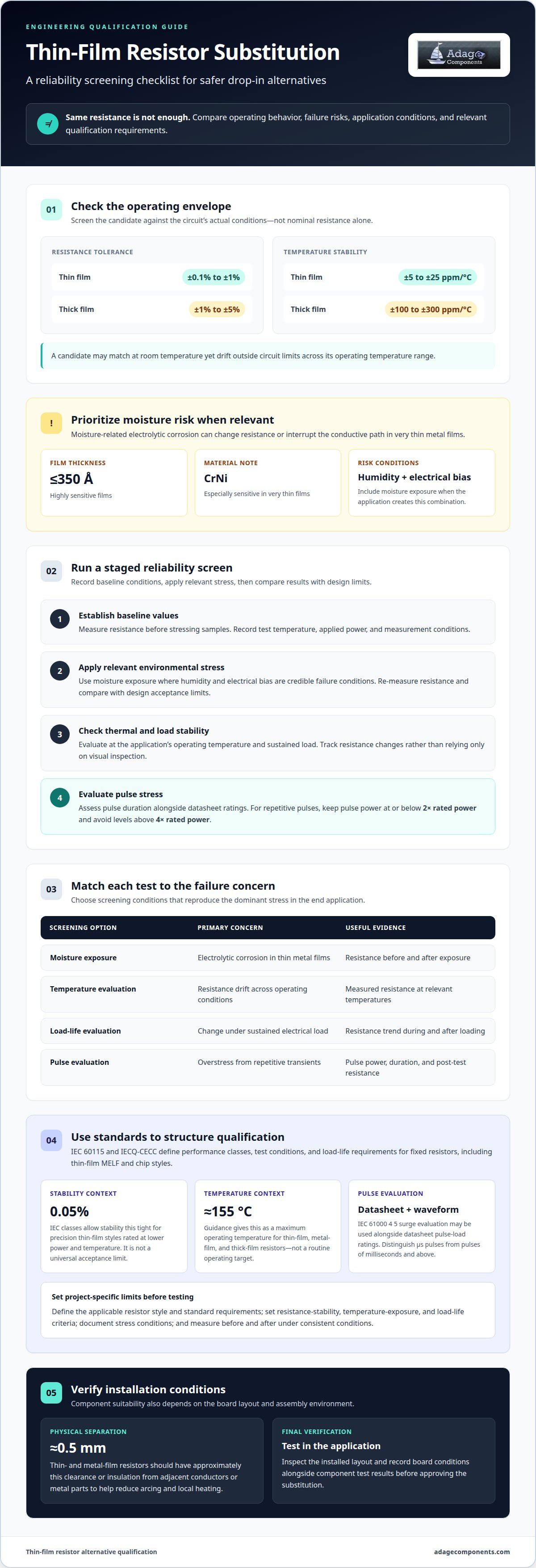
Moisture-related electrolytic corrosion is a key risk in very thin metal films. Films measuring ≤350 Å are highly sensitive, especially when the resistive material is CrNi. Under humid, electrically biased conditions, corrosion can change resistance or interrupt the conductive path. Include moisture exposure in qualification when the application creates that combination of humidity and voltage. A drop-in testing protocol for alternative thin film resistors should prioritize this stress when the operating environment makes it relevant.
Start with the replacement’s operating envelope, not its nominal resistance alone. Thin-film resistors typically have resistance tolerance of ±0.1% to ±1%, while thick-film parts typically have ±1% to ±5%. Temperature stability also differs: thin film generally ranges from ±5 to ±25 ppm/°C, compared with ±100 to ±300 ppm/°C for thick film. A candidate can fit electrically at room temperature yet drift outside the circuit’s limits across its actual temperature range.
Use a staged reliability screen:
- Establish baseline values. Measure resistance and record the test temperature, applied power, and measurement conditions before stressing samples.
- Apply relevant environmental stress. Use moisture exposure where humidity and electrical bias are credible failure conditions. Re-measure resistance afterward and compare against the design’s acceptance limits.
- Check thermal and load stability. Evaluate the resistor under the application’s operating temperature and sustained load. Track resistance changes rather than relying only on visual inspection.
- Evaluate pulse stress. For repetitive pulses, keep pulse power at or below 2× rated power and avoid levels above 4× rated power. Assess pulse duration and datasheet ratings together.
Physical layout affects reliability too. Thin- and metal-film resistors should have approximately 0.5 mm clearance or insulation from adjacent conductors or metal parts. This separation helps reduce arcing and local heating. Inspect the installed layout, since a nominally suitable component can still face stress from nearby metal or concentrated heat. Record the board conditions alongside component test results.
Use the table to match each screening option to its main reliability concern.
| Screening option | Primary concern | Useful evidence |
|---|---|---|
| Moisture exposure | Electrolytic corrosion in thin metal films | Resistance before and after exposure |
| Temperature evaluation | Resistance drift across operating conditions | Measured resistance at relevant temperatures |
| Load-life evaluation | Change under sustained electrical load | Resistance trend during and after loading |
| Pulse evaluation | Overstress from repetitive transients | Pulse power, duration, and post-test resistance |
Use the drop-in testing protocol for alternative thin film resistors to choose screening conditions that reproduce the dominant stress in the end application. Test the selected resistor in that application before approving the substitution.
Resistor qualification standards
IEC 60115 and IECQ-CECC define performance classes, test conditions, and load-life requirements for fixed resistors. Their coverage includes thin-film MELF and chip styles. Use the applicable class to structure qualification, then compare the candidate’s documented test conditions with the design’s operating demands. A matching resistance value alone does not demonstrate equivalent reliability.
IEC classes allow stability as tight as 0.05% for precision thin-film styles rated at lower power and temperature. That figure provides context, not a universal acceptance limit. Set the project’s resistance-drift limit from circuit accuracy needs, operating temperature, and expected load. Record initial resistance and post-test resistance under consistent measurement conditions.
Temperature limits need the same application-based review. The guidance gives approximately 155 °C as the maximum operating temperature for thin-film and metal-film resistors, and thick-film resistors. Treat this as a component limit, not a target for routine operation. Qualification should account for the local board temperature, nearby heat sources, and power dissipation in the installed circuit.
Pulse evaluation requires both the part’s datasheet ratings and the waveform the circuit applies. IEC 61000 4 5 surge standards may be used alongside datasheet pulse-load ratings. Separate short pulses in the µs range from long pulses of milliseconds and above, because allowable energy depends on pulse duration. A useful test sequence applies representative pulses, measures resistance afterward, and inspects for visible damage. For repetitive pulses, keep pulse power at or below 2× rated power and avoid levels above 4× rated power.
Supplier cost, lead time, and availability vary with specification, order conditions, and supply position. Compare equivalent parts and delivery terms rather than unit price alone. A lower price has limited value if qualification results, production continuity, or delivery timing do not support the program.
Follow this sequence to turn the standards into a controlled qualification record:
- Define the class and scope. Identify the resistor style, relevant IEC 60115 or IECQ-CECC requirements, and the intended application.
- Set acceptance limits. Specify resistance stability, temperature exposure, and load-life criteria before testing begins.
- Document stress conditions. Record pulse shape, duration, repetition, and applied power against the datasheet ratings.
- Compare results. Measure resistance before and after each test, then assess changes against the project limits.
For a sourcing comparison, the resistor product line card can help align available resistor styles with the qualification plan. Choose the candidate whose documented class and test performance meet the circuit’s acceptance limits and operating conditions.
What is a drop-in replacement for a thin film resistor?
A drop-in replacement must preserve the original resistor’s function without requiring a board redesign. The drop-in testing protocol for alternative thin film resistors links that goal to measurable circuit and assembly requirements. Compare more than nominal resistance: check the footprint, termination geometry, electrical limits, and manufacturing process. A resistor may fit the pads yet fail to function interchangeably if it changes circuit accuracy or heat dissipation.
Begin by recording the original component’s electrical and physical requirements. Include resistance, tolerance, temperature coefficient, rated power, package, and termination style. Compare each candidate against the circuit’s acceptance limits, not just the original part’s label. Thin-film resistors typically have tolerance from ±0.1% to ±1%, but the circuit determines which candidate is acceptable. A precision divider, for example, may need tighter resistance stability than a circuit with broader operating margins.
Package identity matters, but matching package size does not establish equivalent performance. A 1206 candidate may fit the existing land pattern yet differ in power handling, thermal behavior, or resistance stability. Confirm body dimensions and terminal placement against the board footprint. Review nearby conductors and metal parts as well. A close mechanical fit can still create layout-related stress if component clearances differ.
Construction provides useful context for comparing candidates. A typical thin-film layer is about 0.1 µm, while a typical thick-film layer is about 100 µm. Similar external dimensions therefore don’t prove similar internal construction or behavior. Film type alone cannot qualify a replacement. Compare documented limits and measured performance with the circuit’s operating requirements, including conditions that could shift resistance or increase component temperature.
Use this comparison sequence to organize qualification:
- Match the electrical function. Compare resistance, tolerance, temperature coefficient, voltage behavior, and rated power against the design requirements.
- Match the physical interface. Confirm package dimensions, footprint, terminal geometry, and board clearances against the installed part.
- Check operating behavior. Assess the candidate under the circuit’s temperature, load, and pulse conditions.
- Run an application trial. Install the candidate in a representative circuit and record its performance under normal operating conditions.
Parasitic capacitance and inductance are not reliable shortcuts for identifying film type. Their effects depend on resistor size and value, and the differences may be too small to distinguish technologies. Evaluate these properties when they matter to circuit behavior, such as in a high-frequency design. Use the drop-in testing protocol for alternative thin film resistors to relate comparison results to qualification criteria and application testing. A replacement qualifies only when its interface and measured behavior meet the design requirements.
How should engineers compare noise, voltage coefficient, and power rating of alternative thin film resistors?
Compare noise, voltage coefficient, and power rating under conditions representative of the circuit. A datasheet comparison can screen candidates, while a bench test shows behavior in the intended configuration. Test the original and alternative parts on the same fixture with identical bias, temperature, wiring, and measurement settings. This helps ensure that any differences reflect resistor performance rather than changes in the setup.
For noise, compare measurements across the frequency range relevant to the design. Record the measurement bandwidth, applied current, and instrument configuration for both parts. In a low-level sensor input, excess noise can obscure a small signal even when nominal resistance matches. Check fixture grounding and external interference, then repeat measurements to distinguish consistent resistor behavior from setup noise.
Voltage coefficient describes how resistance changes as applied voltage changes. Compare the candidate’s stated value and test method with the original component’s data. On the bench, measure resistance at multiple voltage points within the specified operating range, keeping temperature and measurement timing consistent. A voltage-dependent shift may affect a precision divider differently from a circuit using the same resistor at a stable voltage.
Power rating involves more than comparing the headline wattage. Review the datasheet’s rating conditions, temperature dependence, and derating information. Calculate dissipation from the circuit’s voltage and resistance, then compare it with the candidate’s applicable rating. For example, a resistor near a heat-generating component may experience different thermal conditions from the same part on an open test board.
Use a controlled comparison sequence to capture all three characteristics:
- Set the test conditions. Fix temperature, fixture, measurement bandwidth, and instrument settings before testing either part.
- Measure noise. Record the frequency range and applied bias, then compare readings using the same setup.
- Measure voltage coefficient. Record resistance at several applied voltages within the operating range and calculate the change.
- Review power performance. Compare circuit dissipation with the applicable datasheet rating and thermal conditions.
- Apply design limits. Evaluate each result against the circuit’s noise budget, resistance stability needs, and power margin.
Keep the results in one comparison record, including the datasheet revision and test configuration. If a candidate performs differently, identify whether noise, voltage sensitivity, or thermal loading is responsible. This makes the decision traceable and directs follow-up testing toward the actual circuit risk.
If temperature coefficient matters, thin-film resistors typically have a lower temperature coefficient than thick-film resistors. Thin-film resistors are used in electronics, instrumentation, medical devices, and automotive applications where accurate, stable resistance and voltage control are important.
What are the recommended solderability and reflow compatibility tests for replacement resistors?
A replacement resistor must form reliable solder joints on the intended board and withstand the assembly reflow process. Evaluate the component’s terminations, solder paste, land pattern, and production profile together. A resistor that measures correctly before assembly can still develop open joints, poor wetting, or movement during reflow.
Begin with a solderability assessment using the actual termination finish and production soldering method. Before placement, inspect representative samples for oxidation, contamination, or damage. Apply production solder paste to the intended PCB land pattern, place the resistor, and inspect the joints after soldering. Check for continuous wetting across each termination and pad, with no visible dewetting or bridging.
Use the production board when possible. A test coupon can help isolate the resistor, but may not reproduce the final design’s pad geometry, copper area, or nearby thermal mass. For example, a small pad connected to a large copper plane may heat differently from an isolated coupon. Record the board layout and paste process with the inspection results.
To assess reflow compatibility, compare the candidate’s datasheet requirements with the assembly line’s established profile. Instrument a representative board to capture the temperature near the resistor, then confirm the profile remains within the component’s stated limits. Do not assume a profile suitable for the original resistor will also suit a replacement with different dimensions or construction.
After reflow, inspect each termination for solder coverage, alignment, cracks, and component damage. Measure resistance before and after assembly under consistent conditions. A shift may indicate thermal or handling stress, while a visually sound joint does not establish electrical stability on its own. Include both inspection and electrical results in the qualification record.
Run the evaluation in a controlled sequence:
- Prepare samples. Use the replacement resistor, production PCB or representative coupon, and the intended solder paste.
- Apply the assembly process. Use the planned placement and reflow method, recording the measured profile.
- Inspect the joints. Check wetting, coverage, alignment, bridging, and visible damage under suitable inspection conditions.
- Verify electrical performance. Compare pre-assembly and post-reflow resistance, then document any change against project acceptance limits.
- Repeat with production-representative conditions. Confirm the result on the board layout and process intended for manufacture.
Keep the sample identity, PCB revision, solder paste, profile data, and inspection findings together. This makes differences between the original component and replacement traceable. Align your shortlist with the relevant resistor product options before planning the assembly trial.
Adage Components: Thick Film Chip Resistors
Adage Components helps teams source Thick Film Chip Resistors and Thin Film Precision Resistors with manufacturer pricing and OEM pricing designed for cost-conscious procurement. We also offer Carbon Film Resistors and MELF Resistors. Our partner suppliers include manufacturers franchised by top 100 distributors, supporting authentic component sourcing and commercial and automotive grade components. We work with ISO certification requirements appropriate to the components and their manufacturing partners.
Our international logistics program and growing state-of-the-art warehouse support short lead times and integration with your MRP system, helping coordinate delivery to your facility. This gives procurement teams a practical route from qualification to sourcing without losing sight of quality or supply continuity.
Contact Adage Components to discuss your resistor requirements and sourcing priorities.
Move the qualified alternative toward implementation
Use the qualification record to guide the next engineering and procurement decisions. Once a candidate meets the design’s acceptance criteria, align its approved specification with sourcing and lifecycle planning. This keeps the substitution tied to production needs instead of treating bench results as the final step. The drop-in testing protocol for alternative thin film resistors is most useful when its findings support a clear component choice and controlled transition.
Adage Components offers Thick Film Chip Resistors, Thin Film Precision Resistors, and Carbon Film Resistors for programs evaluating resistor options. Share your component requirements and sourcing priorities to continue the evaluation with a focused shortlist.
Review resistor options with Adage Components and move your qualified selection forward with confidence.
Frequently Asked Questions
Which electrical and physical specifications must match when replacing a thin film resistor?
Match the circuit’s required resistance, tolerance, temperature coefficient, voltage coefficient, and power rating. Compare package dimensions, termination geometry, and compatibility with the intended soldering process as well. Include operating-temperature and pulse requirements when relevant to the application. For example, a resistor may fit the board footprint but dissipate heat differently. Treat the approved layout and assembly process as part of the specification, not merely the component’s catalog description.
What tests verify resistance value, tolerance, TCR, and long-term stability?
Measure resistance with a calibrated instrument and compare the result with the nominal value and tolerance. Determine TCR by measuring resistance at controlled temperatures, then calculate the change across those conditions. For stability checks, record baseline values before relevant load or environmental exposure and repeat the measurements afterward. Keep the fixture, temperature, and measurement settings consistent. A dated record for each sample helps distinguish component drift from changes in the test setup.
What standards govern qualification and reliability testing of thin film resistors, such as AEC-Q200 or MIL-PRF-55342?
IEC 60115 and IECQ-CECC define performance classes, test conditions, and load-life requirements for fixed resistors, including thin-film chip and MELF styles. Select the qualification scope that matches the program’s requirements instead of assuming one standard covers every application. For surge evaluation, IEC 61000 4 5 may be used alongside the resistor’s datasheet pulse-load ratings. Keep the selected standard and test conditions documented in the qualification record.
What sample size and acceptance criteria are appropriate for a resistor drop-in qualification protocol?
Set sample size through a documented sampling plan that reflects lot variation, test type, and the consequences of failure. Destructive stress tests and production screening may need separate sample groups. Define acceptance limits before testing, including allowable resistance change, electrical continuity, and visible damage after assembly. For example, set separate pass criteria for environmental exposure and reflow inspection. Record sample identifiers and outcomes to keep every result traceable to its lot.
What risks arise when replacing thin film resistors with parts from another manufacturer?
Different manufacturers may use different materials, process controls, or termination construction, affecting circuit behavior and assembly results. A candidate may pass an initial resistance check but behave differently after temperature exposure or production reflow. Documentation and lot traceability matter too: without them, engineering teams may have difficulty linking a failure to a specific component batch. Manage the risk by evaluating samples under application conditions and retaining the supporting test records.
Disclaimer
Cross-referenced components needs to be confirmed by the client with either spec. sheet or samples or both.
Please note, we use AI to help us, information is verified to be correct but we can not guarantee 100% accuracy.


