

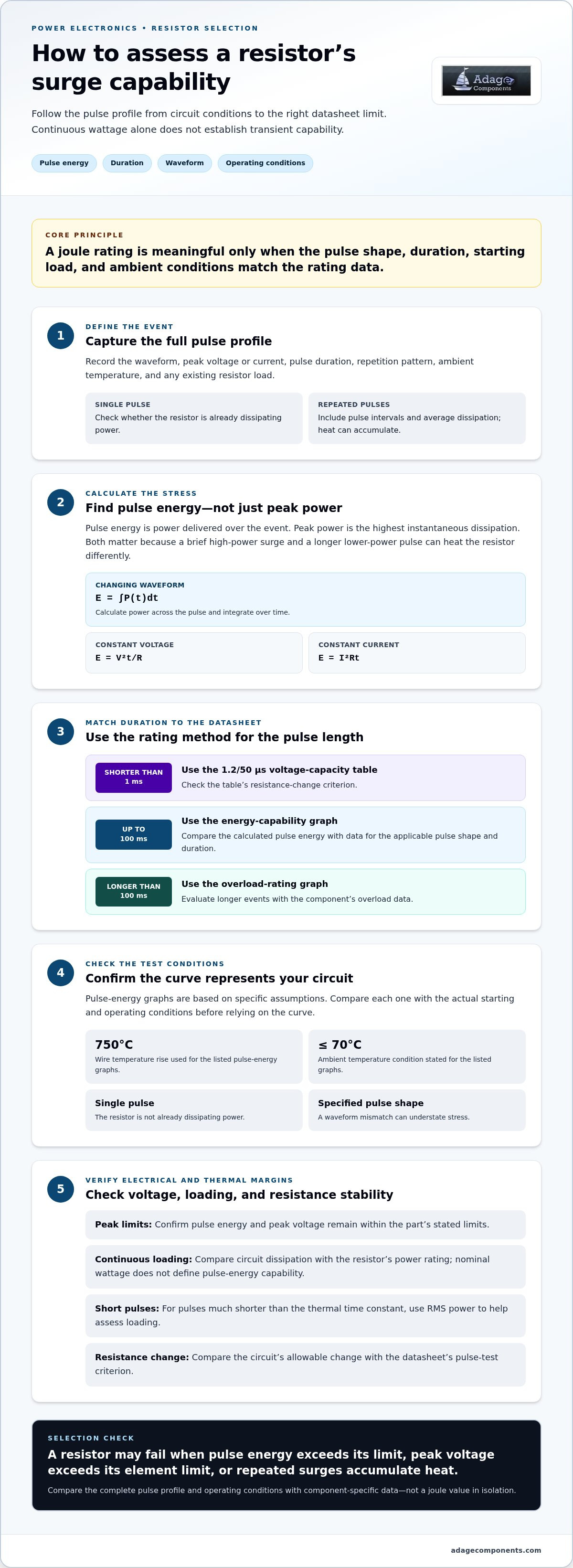
A wirewound resistor’s nominal wattage is not its pulse rating. Wirewound resistor surge capability in power electronics depends on pulse energy, duration, waveform, and operating conditions. For pulses up to 100 milliseconds, use the energy-capability graph; for longer pulses, use the overload rating graph. Pulses shorter than 1 millisecond call for the 1.2/50 μs table.
It’s easy to focus on joules alone, but pulse duration and resistor construction also determine how much transient energy a component can tolerate. This guide explains how joule ratings, pulse limits, and long-pulse overload capability work, and how physical size and thermal conditions affect resistor selection. You’ll see how these factors come together when choosing resistors for power supplies, voltage regulators, and motor drives.
Key Takeaways
- Assess pulse energy alongside voltage, duration, and circuit power dissipation; a resistor’s continuous wattage alone doesn’t establish its transient limit.
- Match the evaluation method to pulse duration: energy-capability graphs apply up to 100 milliseconds, while longer events call for overload-rating data.
- For pulses shorter than 1 millisecond, use the 1.2/50 μs voltage-capacity table and account for its resistance-change criterion.
- Consider the resistor’s construction and physical size when comparing pulse performance; larger bodies generally handle pulsed power better.
- For a more reliable design, assess the full pulse profile and operating conditions rather than selecting by joule rating alone.
Information needed to determine a Joule rating
A pulse rating depends on energy, voltage, duration, repetition, and the resistor’s starting conditions. To assess wirewound resistor surge capability in power electronics, match the circuit’s pulse profile to the resistor’s stated test conditions.
Pulse Rating Assumptions
A pulse rating describes performance under defined electrical and thermal conditions. Those assumptions matter because an isolated pulse differs from repeated pulses or a resistor already dissipating power. For example, applying 200 volts for 1.5 milliseconds produces 270 joules in a W22-R22 example. Derating depends on ambient temperature, initial loading, repetition, waveform, and permitted resistance change, not one universal percentage.
Pulse Test Standards
Pulse-load capability is defined through test waveforms, acceptance limits, and component-specific data. The 1.2/50 μs voltage-capacity waveform is defined in IEC 61000-4-5 and ANSI C62.41. It has a 1.2-microsecond rise time and a 50-microsecond 50% amplitude pulse width. The test permits a maximum resistance change of 2%. These conditions help compare a specified surge test with the circuit transient.
Pulse Timing Effects
Pulse duration affects how much heat spreads through the element during each event, while repetition rate determines how much cooling time is available between events. For pulses much shorter than the resistor’s thermal time constant, RMS power helps assess loading. Repeated pulses can accumulate heat, so include pulse intervals and average dissipation. A single-pulse rating cannot describe a repetitive waveform without those timing details.
Resistance Value Effects
Resistance affects current and energy according to whether the circuit is voltage-driven or current-driven. At fixed voltage, lower resistance draws more current; at fixed current, higher resistance dissipates more power. Compare the circuit’s drive condition with rating data for the selected value. Wirewound resistors commonly have ±1% to ±5% tolerances, which can shift actual current and dissipation.
For power-rating selection, match continuous wattage to expected circuit dissipation. The resistor must handle maximum power without overheating or compromising performance. A W23-43K example gives a 500-volt limiting element voltage and limits continuous power to 5.81 watts. Those values alone don’t establish pulse-energy capability.
When reviewing wirewound resistor surge capability in power electronics, distinguish pulse energy from continuous power. Use RMS loading for pulses much shorter than the thermal time constant, and consider the temperature coefficient when resistance stability matters across a wide temperature range. Check the component data against peak voltage, duration, and operating conditions.
Complete the rating assessment by estimating circuit power dissipation and comparing it with the resistor’s power rating. The resistor must handle the expected power without overheating or compromising performance. Assess continuous dissipation alongside pulse conditions, and ensure maximum operating power stays within the component’s limits. The selection should meet the circuit’s demand without exceeding the resistor’s ability to operate safely. Use this comparison together with the pulse conditions under review.
Transient energy tolerance
Transient energy tolerance describes the pulse a resistor can absorb without exceeding its specified limits. A datasheet curve applies only under its stated pulse shape, starting load, and ambient conditions. Match those assumptions to the circuit before comparing joule ratings.
Pulse Energy and Peak Power
Pulse energy is the power delivered over the event, while peak power is the highest instantaneous dissipation. Both matter: a brief, high-power surge and a longer, lower-power pulse can produce different energy and heating. No single peak-power figure applies to every wirewound resistor. Use the specific part’s pulse-energy graph and electrical limits to determine whether the circuit’s transient falls within its rating.
Surge Energy Calculation
Calculate surge energy by integrating instantaneous power across the pulse: E = ∫P(t)dt. For constant voltage across resistance, use E = V²t/R; for constant current, use E = I²Rt. For a changing waveform, calculate power at each point and integrate over time. Compare the result with the resistor’s datasheet curve for the applicable pulse shape and duration.
Surge Failure Causes
A resistor can fail if pulse energy exceeds its permitted limit, peak voltage exceeds its element limit, or repeated surges cause heat to accumulate. The initial load matters too: single-pulse guidance assumes the resistor is not already dissipating power. A mismatch between the circuit waveform and the tested pulse can therefore understate stress, even when the calculated energy appears acceptable.
Read pulse-energy graphs with their test assumptions. The listed graphs are based on a wire temperature rise of 750°C, with a single pulse applied to a resistor not already dissipating power and at an ambient temperature of 70°C or less. A warmer starting condition or pre-existing load changes the available thermal margin, so the graph cannot be treated as a universal rating.
Precision requirements also affect selection. Resistance tolerance changes actual current and dissipation, while temperature shifts can alter resistance during operation. Compare the circuit’s allowable resistance change with the datasheet’s pulse-test criterion. A resistor that survives electrically may still fall outside the design’s precision requirement after a surge.
For design review, record the waveform, peak voltage or current, pulse duration, repetition pattern, ambient temperature, and existing resistor load. Those inputs connect the circuit calculation to the manufacturer’s curve and expose conditions that a joule figure alone misses. For a component comparison, use the resistor component line card alongside the pulse requirements in your design.
A commenter reported accidentally operating 300W wirewound resistors until they glowed red hot for a few seconds, after which they survived. That account is an observation of one event, not a substitute for the part’s specified transient limits or pulse-energy curve. Survival in that instance does not establish how much energy was absorbed, whether the resistor’s resistance remained within tolerance, or whether repeated operation would have the same outcome. Treat visible survival as distinct from verified electrical and precision performance, and base qualification on the component data and circuit conditions.
Wirewound resistor construction and pulse rating
Construction affects how a resistor handles transient heating and electrical stress. Compare the element design and pulse data for the exact component, not just its resistor family.
Wirewound Construction
A wirewound resistor uses resistive wire, typically nichrome or constantan, wound around a ceramic or fiberglass core. The element and core carry current and absorb pulse energy. This construction helps explain why many wirewound parts have good pulse-power specifications, but it does not establish a universal surge rating. The component’s geometry and manufacturer’s test data still determine suitability.
Datasheet Surge Specifications
A datasheet defines surge performance through component-specific pulse curves, test conditions, and electrical limits. Check the pulse waveform, duration, resistance value, and permitted resistance change alongside any energy or overload graph. The wirewound category alone does not provide a usable joule limit. Pulse-handling capability varies substantially, so consult the manufacturer’s handbook or datasheet for the exact part.
Material comparisons need the same care. Thin-film resistors generally have relatively poor pulsed-power specifications, while metal-oxide power resistors and most wirewound resistors have good pulse-power specifications. Compare metal-film and thick-film parts against their own pulse data; a material label alone does not establish equivalent performance. Match the specified test to the circuit’s voltage and pulse profile.
Read each curve as a limit under stated conditions, not as a general promise for every waveform. For example, a pulse-energy graph may show allowable energy against pulse duration. A separate overload graph may cover a different operating regime. Keep these data sets distinct: using the wrong curve can make a design appear more tolerant than its tested limits support.
Construction informs the design review, but it does not establish allowable temperature rise or resistance shift. Nichrome or constantan wire wound on a ceramic or fiberglass core identifies the resistive element and support; the specific part and test method determine its performance. Compare the pulse rating with the circuit’s peak stress, then check whether the resulting resistance change is acceptable for the application.
For a practical comparison, record the part number, resistance, pulse duration, waveform, and datasheet limit in one review table. Compare wirewound, metal-oxide, metal-film, and thick-film candidates under equivalent conditions. If a datasheet lists only continuous power, that value alone cannot define pulse capability. The pulse curve or test specification must correspond to the transient being evaluated.
Long-pulse overload capability
A long pulse stresses a resistor through sustained heating, not only its instantaneous peak. For pulses longer than 100 milliseconds, use the overload rating graph rather than the pulse-energy graph. That distinction matters because longer events allow heat to spread through the resistive element and surrounding structure during operation.
Read an overload curve in relation to both pulse duration and applied load. It shows how much temporary power the component can tolerate under its stated conditions, but does not replace the continuous power rating. A resistor may tolerate a brief overload yet exceed its thermal limits if the load continues or recurs before sufficient cooling.
Start by mapping the circuit’s power profile over the entire event. With steady voltage across a fixed resistance, power remains approximately constant; with changing voltage or current, calculate dissipation over time. Compare the resulting load and duration with the manufacturer’s overload graph. This distinguishes a long, moderate overload from a short surge with a high peak.
Repetition changes the resistor’s thermal starting point. If another pulse arrives while the resistor is still warm, it has less capacity to absorb additional energy than it would from a cool state. Include the interval between events, background circuit load, and surrounding temperature in the assessment. A rating for one isolated overload does not automatically represent a repeated pulse train.
Continuous dissipation also affects the available overload margin. A resistor already operating near its rated power has less thermal headroom for an added event than one carrying a light load. Evaluate the normal operating load first, then assess the temporary increase. The relevant comparison is the resistor’s total stress during the event, not overload power in isolation.
For a practical review, record the overload duration, voltage or current profile, repetition pattern, ambient conditions, and existing dissipation. Then select the overload curve that matches the component and operating conditions. If the datasheet provides only an energy graph for pulses up to 100 milliseconds, that graph does not establish long-pulse capability; use overload data for the longer event.
Derating depends on the difference between the circuit’s actual conditions and the curve’s test conditions. Higher ambient temperature, existing power dissipation, or shorter recovery intervals reduce thermal margin. Apply the component’s published conditions and limits rather than assuming a fixed derating factor. This helps distinguish a tolerable temporary overload from sustained operation that can cause excessive heating or resistance drift.
Optimizing resistor designs for pulse capability
Improve pulse capability by choosing a resistor and designing the circuit around the same stress conditions. The practical goal is to reduce thermal and electrical strain, rather than treating nominal wattage as a complete design target.
Physical size is a useful starting point. Larger resistors generally handle pulsed power better than smaller ones because their construction can provide more material and thermal capacity. Compare available body sizes with the circuit’s pulse profile, then evaluate each candidate’s actual pulse data. A larger case alone does not establish suitability, but it can help narrow the design review.
Shape the load where the circuit allows it. For example, an inrush-limiting path can reduce initial current compared with a direct connection. A slower voltage ramp can also reduce abrupt dissipation in the series resistor. Recalculate the waveform after any circuit change, because reducing peak current may alter pulse duration and total energy.
Placement affects heat flow. A resistor mounted close to another heat-producing component faces different thermal conditions from one with clear spacing and airflow. Review nearby power devices, copper areas, enclosure conditions, and board orientation as part of the design. These layout details affect how efficiently heat leaves the resistor during operation and between recurring events.
Choose resistance and circuit topology together. In a voltage-driven path, lower resistance increases current; in a current-driven path, higher resistance increases dissipation. If the design uses multiple resistors, assess current sharing and whether tolerances could concentrate stress in one component. Evaluate the network as installed, not as an ideal schematic with perfectly matched parts.
Define acceptance criteria before comparing components. Record the application waveform, normal operating load, ambient conditions, and allowable resistance shift. Then compare each candidate’s pulse limits with those requirements. If a design change modifies the waveform, update the comparison rather than relying on the old result. This provides a traceable basis for engineering review and component qualification.
Thermal margin also depends on the duty pattern. A resistor exposed to recurring pulses may start each event warmer than one tested with an isolated pulse. Consider the actual cooling interval and steady-state dissipation together. For example, reducing pulse repetition or background load can improve recovery between events without changing the resistor itself.
Use the final design review to connect circuit-level changes with component evidence: size, mounting, waveform, and operating load. For component selection across resistor technologies, compare the available resistor component options against the application’s pulse requirements.
Adage Components: Thick Film Chip Resistors
Adage Components supports resistor sourcing with Thick Film Chip Resistors, Thin Film Precision Resistors, Carbon Film Resistors, and MELF Resistors. For OEM and EMS procurement, its direct procurement channels provide authentic components and manufacturer pricing, with OEM pricing designed to deliver the advantages of tier-one distribution at a manufacturer level.
Quality assurance includes manufacturing audits and partner suppliers, many franchised by top 100 distributors. Adage Components also supports commercial and automotive grade components and international logistics, helping procurement teams manage component supply and lead times. These capabilities can be useful when a bill of materials requires a cost-conscious alternative while maintaining sourcing and quality requirements.
For resistor options aligned with your requirements, contact Adage Components.
Make Pulse Requirements Part of Design Control
Treat pulse analysis as a documented design input, not a one-time component check. Record the operating assumptions alongside the selected part so future design revisions can account for changes to the load, layout, or operating environment. This makes wirewound resistor surge capability in power electronics easier to reassess when the circuit or sourcing requirements change.
Keep selection criteria clear for engineering and procurement. A shared record helps teams compare alternatives against the same application requirements and avoid treating different test conditions as equivalent. It also gives reviewers a defined basis for assessing component substitutions during lifecycle changes.
For the next sourcing step, review resistor options with Adage Components and align your component search with the design requirements. A clear selection record gives your team a practical starting point for continued design control.
Frequently Asked Questions
How to select and price a wirewound resistor for power electronics surge protection?
Select a part by matching its pulse data to the circuit waveform, then request pricing for the exact specification and order requirements. Include the resistance value, continuous power needs, peak voltage, pulse duration, and repetition pattern in your component review. For a useful quote, provide the manufacturer part number or a complete technical description with your RFQ. Adage Components offers wirewound resistors for power electronics sourcing.
Disclaimer
Cross-referenced components needs to be confirmed by the client with either spec. sheet or samples or both.
Please note, we use AI to help us, information is verified to be correct but we can not guarantee 100% accuracy.


